Written by John Polakowski
There are two primary energy storage mediums in electrical engineering: Inductance and Capacitance. This will be an examination of the effects observed when time varying Inductance or Capacitance in a cyclical manner.
Introduction
When considering Inductance and Capacitance, one normally thinks about lumped elements in a circuit. These lumped elements are storage facilities for electrical energy. Inductors and Capacitors “store” energy within their structure, this in the form of potential energy. Inductors store potential energy in the form of the magnetic field, and capacitors store potential energy in the form of the dielectric field. The terms Inductance and Capacitance are basically co-efficients of how much potential energy can be stored in the respective fields of Inductors and Capacitors. The larger the Inductance or Capacitance, the larger the amount of potential energy can be stored in the element. A coil with a large inductance can store more magnetic field energy(magnetic lines of force, or magnetic flux lines) than a coil with a smaller inductance.
There are two well known equations relating the potential energy stored.
For Capacitance:
![]()
For Inductance:
![]()
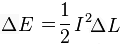
If the inductance is instantaneously increased by an amount delta L, the potential energy stored in the inductor is increased by:
This paper will be an investigation into the variation of the storage parameter Inductance; however the concepts are applicable to the variation of Capacitance as well.
Review of Inductance
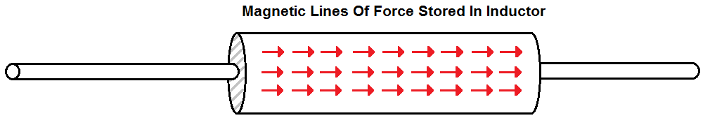
Consider an induction coil:

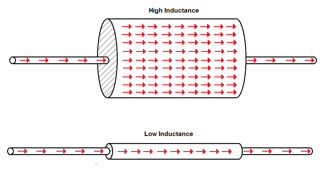
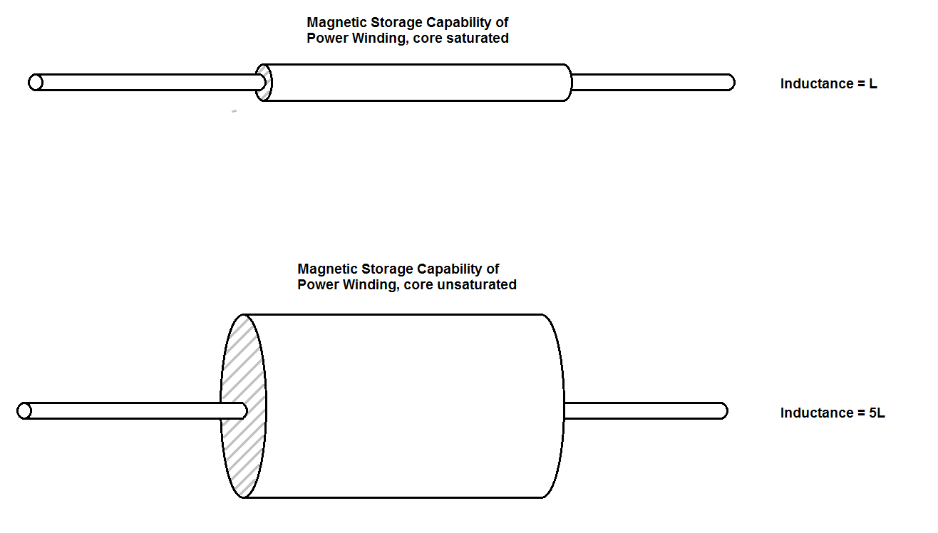
The amount of potential energy it can store is directly proportional to the amount of magnetism the coil can store. The red arrows below represent magnetic lines of force, or the magnetic induction, and serve to illustrate the amount of magnetism the induction coil can store within its geometry:
The more magnetism an Inductor can contain, the higher it’s Inductance:
When a current i begins to flow through an induction coil, current is exchanged into its magnetic field. This is seen as a voltage drop across the coil. The field does not immediately rise to its final value instead it increases proportional to the current flowing through the coil. As soon as current reaches its maximum value, there ceases to be a voltage drop across the coil due to the magnetic field increasing, the field has reached its maximum value. The inductor attempts to keep the current flowing through the coil constant. If the current source to the coil is suddenly cut, the magnetic field of the coil is exchanged back into current, until the magnetic field of the coil is depleted. Energy is conserved, that is there is no “free energy” by capturing the voltage spike of the coil.
EMF production Equation
![]()
Factors That Affect Inductance
The inductance of a given coil is given by the relation:
![]()
A is the sectional area of the magnetic induction, in centimeter square
n^2 is the total flux inter-linkages between the current, i, and the magnetic induction, Phi.
sigma is the effective permeability, a numeric.
For a unit turn the relation becomes,
![]()
Looking at the parameters that affect inductance, we can change the inductance by altering the number of turns, the effective permeability, or the cross sectional area of the core. Physical limitations prevent changing the cross sectional area of the core, so for our purposes the inductance can be changed by either varying the effective permeability of the core, or the number of turns of wire surrounding the coil. For the purposes of this discussion the number of turns on the power winding will be considered static. In the case of varying the effective permeability of the core, it can be varied in one of two ways:
1) Saturating the core with flux .When the core is saturated the core can’t contain any more flux and the permeability is reduced to that of free space
2) Inserting/Removing core material into the center of the coil. This increases the effective permeability of the coil from that of air, to the permeability of the core material inserted.
A Magnetic Amplifier functions by saturating the core with flux, varying the permeability, and will be considered here. In the paper: “Parametric Excitation of Electrical Oscillations”, Mandelstam and Papalexi, inductance modulation was accomplished by alternately inserting and removing core material in the coil’s windings.
The Magnetic Amplifier
The magnetic amplifier, or MagAmp, is basically a variable inductance coil. The MagAmp varies its inductance by changing the relative permeability of the core. The MagAmp serves as an amplifier by varying its inductive reactance to alternating current. It has three primary components: a power winding, a control winding, and a common core. In a conventional magnetic amplifier there are two power windings, connected in parallel, but opposite in phase:
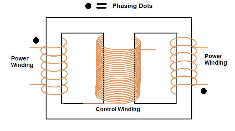
Notice the control winding has significantly more turns than the two power windings. This is done so the maximum amount of magnemotive force can be created to saturate the core using the least amount of current in the control winding. Also a lower turns count in the power windings prevents the core from being easily saturated due to current flowing in the power windings. This comes at the expense of lowering the inductance of the power windings however.
![]()
Also notice the two power windings are wound in opposite directions. When the power windings are connected in parallel, the flux they generate will cancel in the central core leg:
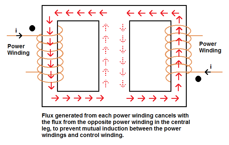
Additionally, this prevents the frequency of current in the power windings from showing up in the control winding. This is how a conventional MagAmp is connected:
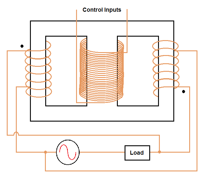
The MagAmp functions as an amplifier by varying the reactance of the power windings. If more load current is desired, current is passed through the control winding, the core is saturated, the inductance of the power windings is reduced, and the reactance of power windings is lowered, so more current can flow. The amplification factor of a MagAmp depends on the number of turns of the control winding, and the permeability curve of the core.
Theory of Energy Synthesis by Varying the Parameter Inductance:
Previously we determined the potential energy stored in the magnetic field of the induction coil to be:
![]()
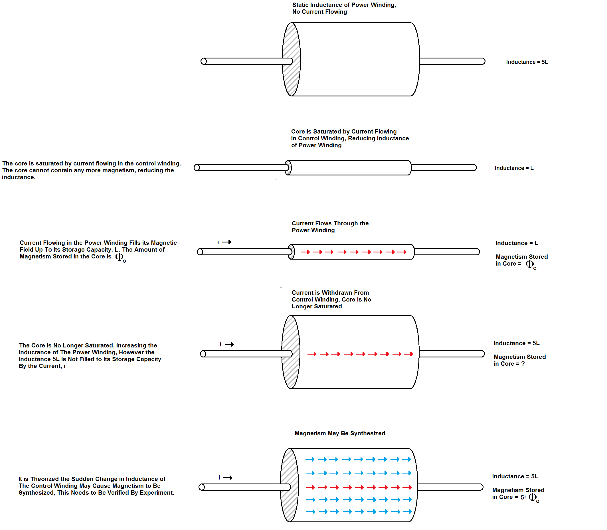
A pre-requisite for current to have reached the value i in the induction coil, is the magnetic field of the coil has also reached a magnitude corresponding to the amplitude of i and the storage capacity L. The magnetic field of the coil grows in step with the current flowing through it. By varying the inductance for a given value of i, we are trying to decouple the amount of magnetism stored in the coil from the amount of current that is required to create it. We are attempting to decouple the effect(amount of magnetism stored in the coil) from the cause(quantity of current required to create the magnetic field).
The amount of magnetism that can be stored in the core whether or not the core is saturated can be seen as:
The objective is to synthesize magnetism stored in the magnetic field of the power winding. It is theorized this can happen as follows:
An analogy may be made for the condition of magnetism suddenly being “synthesized” in the core. The inductance can be compared to a hand pump. A hand pump works by changing the amount of air the pump can hold. As the plunger is pulled back, the pump body volume expands, drawing air into the pump. When the plunger is pushed forward, the amount of air the pump can hold is decreased, which either causes an increase in pressure or air to be expelled from the pump. In the same way, increasing the inductance of a coil causes magnetism to be “drawn in” to the core, by virtue of increasing its storage capacity.
Amount of Magnetism Synthesized:
The Magnetic Induction stored in the field of an inductor is given by the following relation:
![]()
It can be seen increasing the inductance by an amount delta L, the magnetic induction is increased by the amount:
![]()
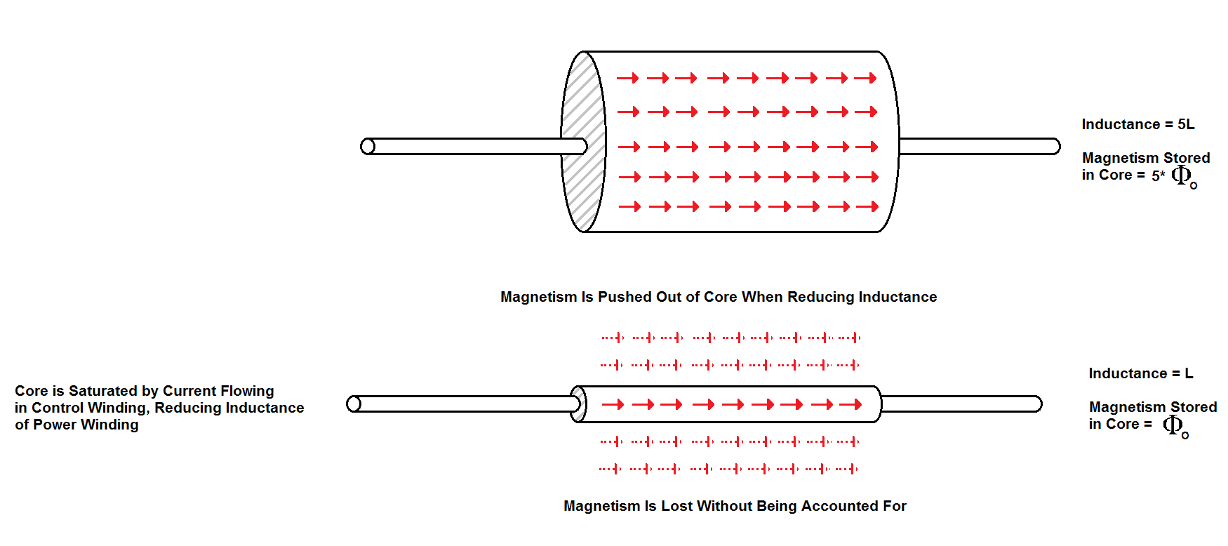
By the same reasoning, if magnetism can be synthesized, it can also be destroyed, without it being dissipated as heat or by some other means. For a decrease in inductance, the magnetic induction present is decreased by the amount:
![]()
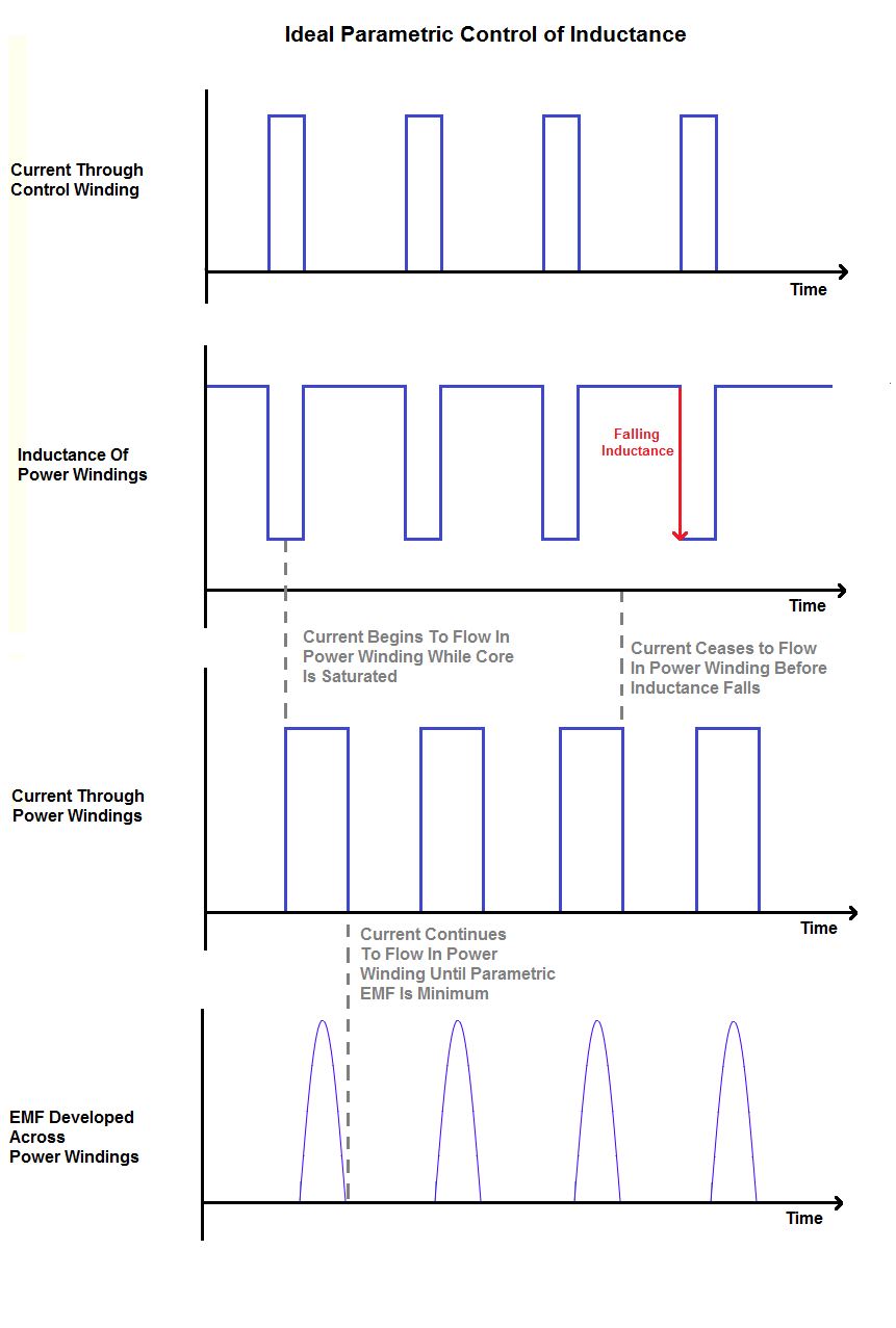
For this reason there should be no current flowing in the power winding during a falling inductance. Loss of Magnetism:
EMF Developed Across the Power Winding:
When an EMF is developed, there is an energy transfer into or out of storage in the magnetic or dielectric field. With the MagAmp we are dealing with energy transfer into and out of the field of magnetism. A change in the quantity of magnetism present generates an EMF. When an EMF appears there is an exchange of energy from the magnetic field into the dielectric field. The relation is given as:
![]()
For mutual induction involving flux inter-linkage the EMF developed is:
![]()
For a parametric EMF due to inductance variation the EMF is:
![]()
Which indicates a larger parametric EMF is developed due to either a large swing in inductance, or a small period of time in which the change happens. The EMF developed is an EMF of production; that is, it is not a voltage drop but a voltage source.
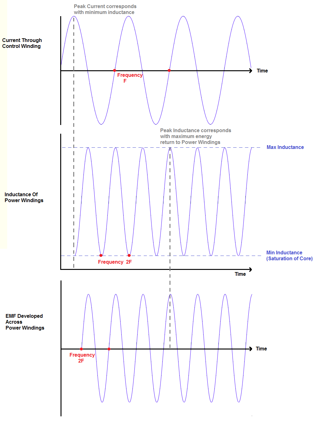
An electric circuit is often compared to a mechanical system for teaching purposes. The MagAmp can be compared to such a system. Consider the mechanical equivalent of a MagAmp: a mass on the end of a spring:
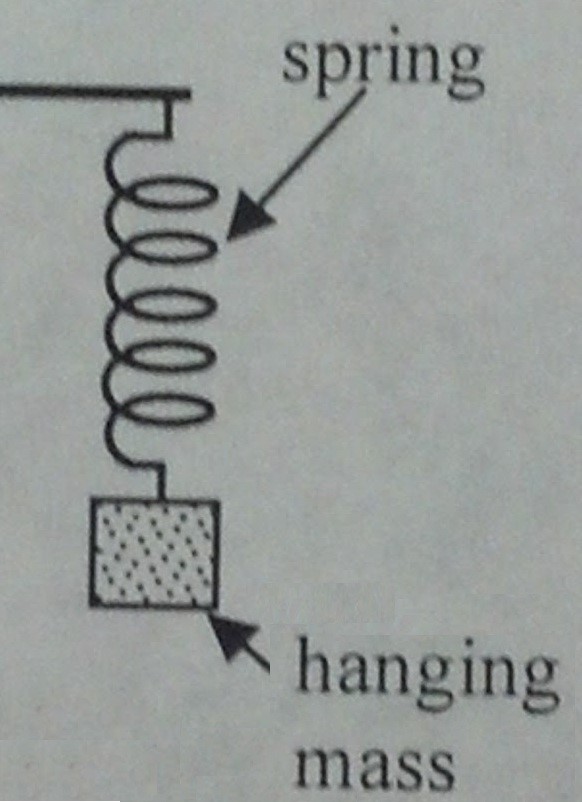
The spring can be compared to a capacitor. There isn’t a capacitor present in the MagAmp, but there is one present in the output circuit of the power windings. The inductance of the power windings is represented by the hanging mass. A heavier mass is equivalent to a higher inductance of the power windings. Suppose the mass is oscillating up and down. The current flowing through the power windings can be compared to the vertical displacement of the oscillations of the mass on the spring. Now we can make the analogy:
1) The mass is oscillating, bouncing up and down.
2) When the mass reaches the bottom, and the spring is extended, the mass is suddenly changed to a very light value.
3) The mass is pulled up by the spring to its peak height.
4) The mass is now suddenly changed to a very heavy value.
5) The mass falls again, to an even lower minimum height than before
One can easily see the oscillations of the system will continue to grow. This is what is happening with the MagAmp. The inductance is varied. However the timing of the inductance change is critical, as it is in the case of the mass at the end of a spring.
The magnetic induction present in the MagAmp power winding is:
![]()
The amount of magnetism synthesized is given as:
![]()
The objective is to maximize the amount of energy returned in the power winding. The net energy gained in the process is the increased power present in the MagAmp power winding circuit minus losses. Losses can be from:
1) The power draw in the control winding circuit
2) Core losses due to hysteresis and eddy currents
3) Resistive losses in the conductors
There are two factors governing the amount of energy synthesized by the MagAmp power windings:
1) The amount of energy synthesized per cycle
2) How fast a cycle can be repeated. The more cycles per second that can be repeated, the greater the energy returns.
Item (1) is determined by the inductance modulation depth and current flowing through the power windings. Item (2) is determined by the amount of time it takes to perform the inductance swing.
Maximizing Inductance Variation for the Purpose of Synthesizing Magnetism
To create the most energy returned in the power winding circuit, dL/dt must be maximized. This causes us to consider the two separate quantities dL and dt. The parameters that influence dL and dt are interrelated.
The term dL , the change in inductance, is called the depth of modulation. To create a large dL, Lmax must be sufficiently large. Looking at the relation for inductance:
![]()
With the MagAmp only the effective permeability is being varied, the turns ratio and core cross sectional area are fixed:
![]()
Maximum del L will result when these parameters are maximized. The quantity A*del permeability relates to the material selection of the core, and it’s size. A larger core can contain more magnetism, thus a higher inductance. The permeability is determined by the material choice of the core. An ideal material for the core has a high permeability, as well as a reasonably square hysteresis loop. It would seem a high turn count on the power windings would be ideal. That would yield a large power winding inductance, as the inductance is proportional to the number of turns squared. There is a tradeoff however. A large turn count also causes a large magnemotive force to be developed in the core from current flowing in the power winding:
![]()
The core can only contain a finite amount of magnetic flux before becoming saturated, so a high turns count will cause the core to become saturated from power winding current earlier than a lower turns count. For the purposes of synthesizing magnetism, the inductance must remain high(core not saturated) even with current flowing in the power windings, as the transition from minimum to maximum inductance occurs with current flowing in the power winding. Thus a high turns count limits the amount of current that can be put into the power winding. However a large current is desirable in the power winding, it takes part in determing the amount of power returned by the inductance swing. As a result the number of turns on the power winding should be minimized. It can be seen the maximum delta L should be obtained by having minimum turns, maximum core size, and good choice of core material with a high permeability.
The quantity dt is the amount of time it takes to make the inductance change. The objective is to make the change as fast as possible for two reasons:
1) The EMF generated on the power winding is directly proportional to the time it takes to for the inductance to change from minimum to maximum.
2) The maximum quantity of energy is returned to the power winding by repeating the cycle of inductance change as quickly as possible. This is limited by the time it takes to make one cycle of inductance variation.
Item (1) is determined by the shape of the waveform on the control winding. Item (2) is determined by the time it takes to get current flowing in the power and control windings. This can be seen in the following timing diagram:
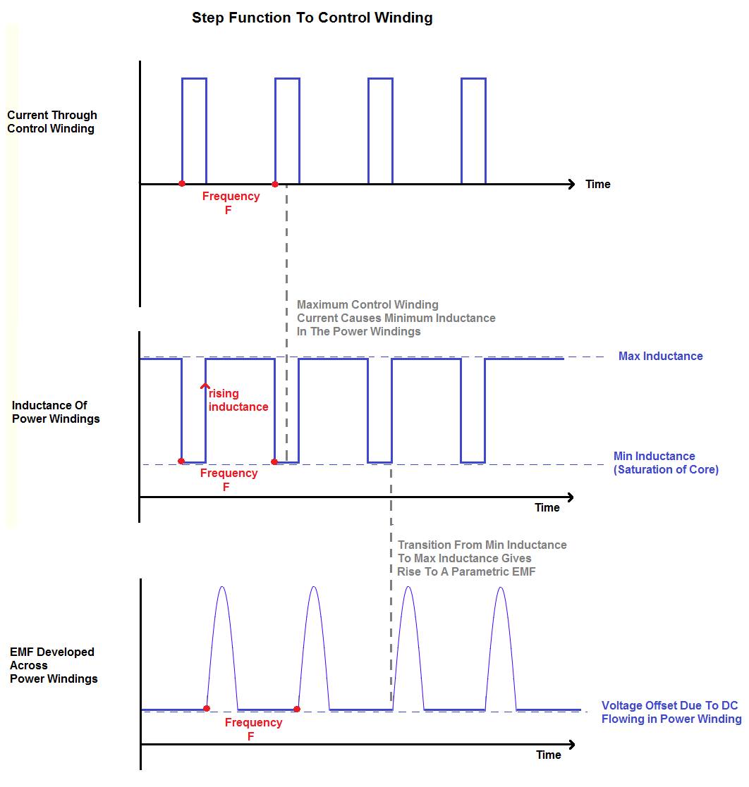
The rise time of the control winding current is determined by the waveform and inductance of the control winding. The control winding inductance should be minimized to reduce the rise time of the current, and saturate the core faster. To reduce the inductance the turns count on the control winding should be minimal. The tradeoff is a lower turn count requires a high control current to saturate the core.
Optimization of MagAmp Design Parameters
Parameter: number of turns, control winding
Optimization: Minimum necessary
Reason: The more turns on the control winding, the larger inductance it has. The larger inductance will resist having a quick current change in the control winding. How fast the current changes is directly proportional to how fast the inductance of the power winding changes. It is desirable to have as quick a current change in the control winding as possible, and thus a quick inductance change of the power winding. To do this requires a minimum number of turns on the control winding. This is counter to a traditional MagAmp which has a large turns count on the control winding, to maximize the amplification factor(current input to control winding vs. current increase in power winding). The tradeoff however is that as the turns count on the control winding is decreased, the required current through it to saturate the core rises.
Parameter: number of turns, power winding
Optimization: Minimum necessary
Reason: The power winding needs a minimum number of turns for two reasons. One is to minimize the magnemotive force created by the current flowing in the power windings. When current is flowing through the power windings, the inductance still needs to be reasonably high, the core cannot be saturated. So the current is limited by the amount of flux it creates in the core. Because the energy returned to the power winding is proportional to the inductance change and the current flowing through it, a large current in the power winding is desirable.
The other reason is a large turn count in the power windings limits the rise time for current. Current must start flowing as soon as the core is saturated, continue flowing during the inductance change, and then stop flowing as soon as the inductance starts falling.
Parameter: current, power winding
Optimization: As high as possible
Reason: The EMF seen across the power windings is:
![]()
A larger current yields a larger EMF, and thus more energy returned to the power windings. The limiting factor to the magnitude of current flow is saturation of the core; the core must not be saturated by the power winding current. The power winding current should set the operating point, where a minimum current flowing through the control winding causes the core to saturate and the inductance to change.
Parameter: waveform, control winding
Optimization: Square wave, particularly the trailing edge
Reason: The largest EMF seen across the power windings will be seen when the inductance is changed as quickly as possible. The change that generates this EMF is from low inductance to high inductance. The condition that causes this is the core being saturated, to not being saturated. The core is saturated when current is flowing through the control winding, and stops being saturated when control winding current ceases. So the portion of the control winding signal we most interested in is the trailing edge of the waveform, which must be as sharp as possible.
Parameter: core size
Optimization: As large as possible
Reason: The parameter that is being varied is the permeability of the core, how much magnetism the core can contain. A large core can contain more magnetism than a smaller core. The core size is directly proportional to the inductance of the power windings. A larger core can allow for more current flowing through the power windings, and for a larger inductance swing to happen. The single greatest factor affecting how much magnetism can be synthesized is the size and material properties of the core.
References
Equipment Built
Experimental Results