(I) There seems to be considerable confusion regarding the Alexanderson Network as a high frequency antenna for radio communications. I constructed the first version of such a network at the “Camp David” Installation on 450 Overlook, Bolinas, CA. This was done from 1990 to 1994. This installation was obliterated by the County of Marin as a service to the Golden Gate National Recreation Area. Pictures of the Alexanderson network, or array, can be found in the “Barbera Boxer Report” by E.P. Dollard. Camp David, named after its owner David Franklin, was conceived as a civil defense facility for the Town of Bolinas. The Camp David antenna is a dual log-periodic Alexanderson network for high frequency radio communications. Hence forth it will be called the “Bolinas Antenna”. The Bolinas Antenna suited the needs of both Bolinas radio stations KPH and NMC. The “group” did not like this idea so the Bolinas antenna is no more. But the principles are not gone, they exist as mathematical certainties and established engineering formula. The Bolinas antenna is constructed upon two primary engineering considerations: The first is the use of counter-spatial, or reactive, elements, as found in the distributed networks of Tesla and the lumped networks of Alexanderson. The second is the use of a log-periodic sequence of elements as developed thru U.S. Air Force research contracts. The union of these two conditions give rise to a broad bandwidth structure along with “Non Maxwellian” transmission capability. Niether Tesla nor Alexanderson produced such a network, both were very much Single Frequency structures.
The primary objective in the development of the Bolinas Antenna was for telluric transmission and reception in the range of 80 to 40 meters, a one octave band. The Bolinas Antenna consisted of a pair of vertical networks in phase conjunction. The neutral connected directly into the San Andreas Fault line. The log-periodic construction allowed the Bolinas Antenna to also be utilized as an electro-magnetic radiator up to 30 megacycles per second. The compact size and the broadband characteristics make this antenna useful for confined shipboard installations. The theory and design as well as construction details will be developed here.
(II) The counter-spatial, or reactive, transmission network theory is already given in “System for the Transmission and reception of Telluric Electric Waves” by E.P. Dollard. This aspect will therefore not be repeated here. The log-periodic concept will however be developed in the following: Considerable detail on the log-periodic antenna can be found in “The Multi-Wave Oscillator Handbook”, by Tom Brown. A U.S. Psychotronics Assn. Video on the M.W.O. Also exists on “YouTube”. Here can be found the details of my U.H.F. M.W.O. Antenna. Its range was from 300 Mc/sec to 1000 Mc/sec. A “faster than light” speed was expected, but as usual it was time for the “rat to run” so the antenna project vanished to the winds. Be we can rest assured that someone profited from it.
The log-periodic antenna grew out of U.S. AirForce research contracts with the objective of developing a “frequency independent” antenna. The tactical H.F. Radio, and the U.H.F. Spread spectrum systems under development could not operate without such an antenna structure. Unexpectedly here electricity meets with Fibonacci. The log-periodic antennae were found to project themselves into a virtual antenna beyond the physical bounds of their apex. This is analogous to the “plant-archetype” of Rudolf Steiner.
Log-periodic theory states that an electrical structure becomes frequency independent when its constituent sub-structures each exist in a log-periodic sequence. This is to say each elemental network in a series of networks differs from its neighbor networks in a constant logarithmic proportion. Then the concatenated series of networks becomes frequency independent over a finite band, this depending on the total number of individual networks in the log-periodic progression, the more networks the greater the bandwidth.
This log-periodic geometry can be seen in a given rank of organ pipes. The musical scale is a log-periodic sequence in itself. The generalized log-periodic form is derived from the following mathematical expression
 , numeric (1)
Theoretically, there is no beginning, nor is there any end to this sequence, and numerically it must equal infinity. One side continues to become smaller and smaller, while the other side continues to become larger and larger. Naturally, only a finite span of this log-periodic sequence can be utilized in any realizable structure. The pipe organ is a good example of a definite log-periodic span. The largest possible pipe is 32 feet. This is taken as the reference pipe. None can be made larger than this, it is the size of a utility pole. Let for the 32 foot pipe, in the “octave” sequence of a equals two, the total rank be given by;
Beginning,


Thus the entire scale of the pipe organ, in octaves of a equals two, is given as
 , numeric (2)
This mathematical expression serves as a finite span, or scale, out of the infinite log-periodic series of octaves. This scales is symbolized by a log-periodic operator,
 , numeric (3)
Expression (3) is both symbolic and also a definite numeric value,
 (4)
(4)
Hereby, for the pipe organ scale, this operator takes the form,
 (5)
(5)
And
 numeric (6)
This eighth order operator hereby expresses the pipe organ in terms of the log periodic scale of octaves.
The generalized log-periodic series can be reduced to the following expression,
 numeric (7)
Thus it is then derived
 numeric (8)
The root log-periodic operator, and this may be regarded as a kind of “alter-versor”.
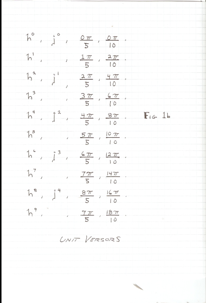
During the development of the log-periodic antenna it was discovered that the optimum scaling factor,  , was approximately 60 percent, giving a log base of near 1.6. Let a given log-periodic base be given by the relation,
 numeric (9)
This is a vector projection derived from the versor expression,
 unit. (10)
This vector is known as the Golden Ratio. The derived log-periodic is the scaled utilized by Nature in organic formative forces. Numerically it is given as,
 numeric.
his is very near the value of 1.6. Taking 5 elements out of the entire Golden Ratio log-periodic series gives the following numeric values;  , beginning


And total,
 numeric (11)
 is the unit size upon which the scale develops. In this case
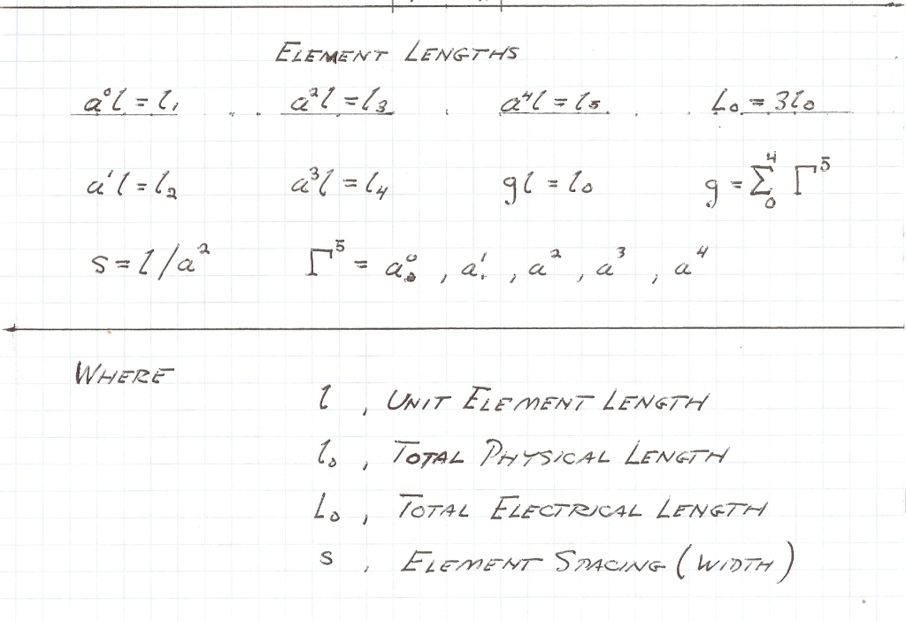
  is the length of the smallest antenna element. Denoting this unit length as l (feet, cm, etc) the log-periodic series is then
 (12)
(12)
Hence the element lengths


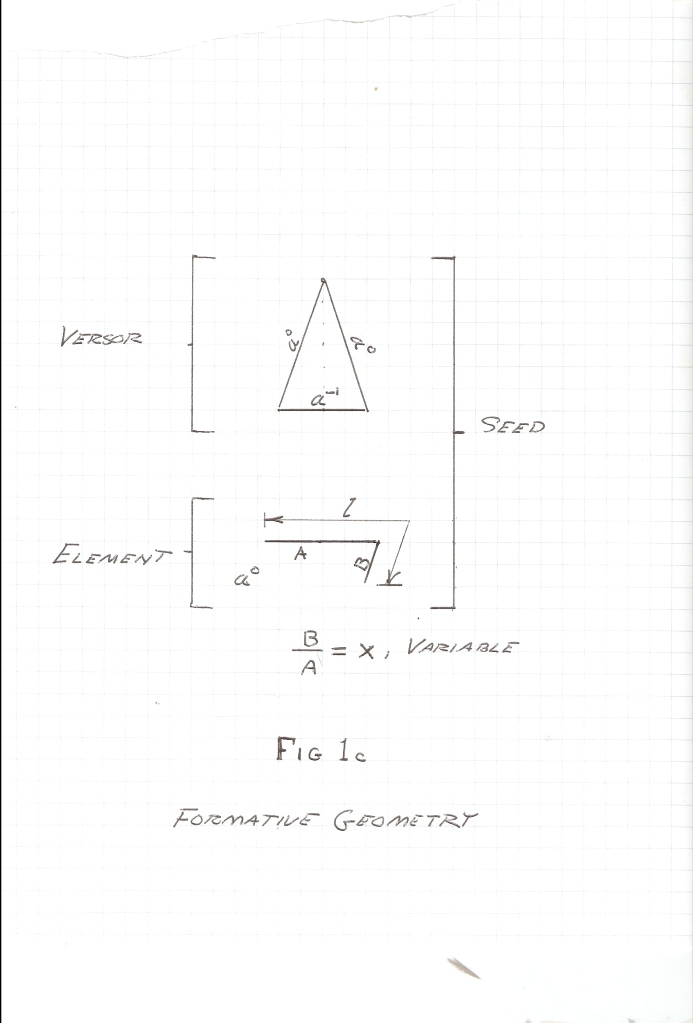
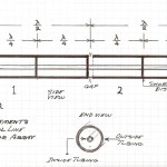
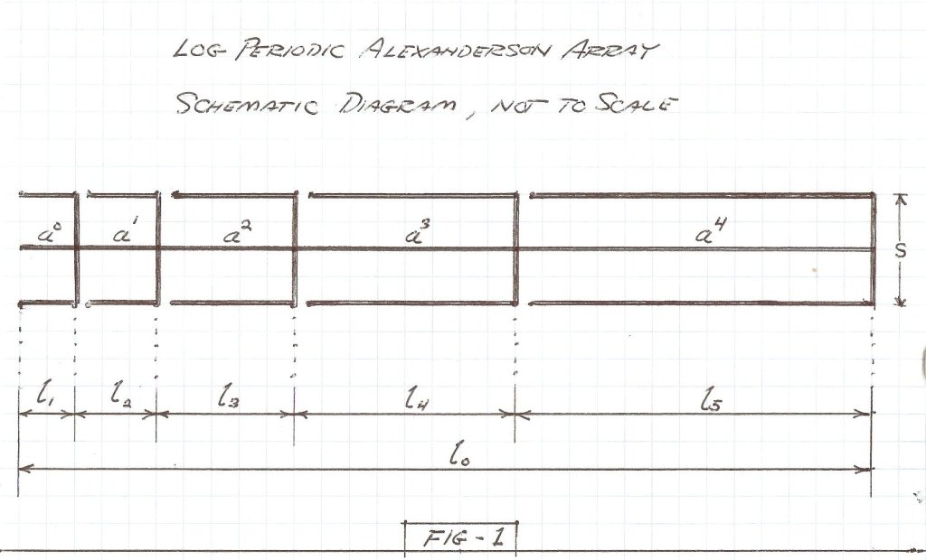
Here given is the five sequential lengths in a five element log-periodic antenna with a scaling factor derived from the fifth root of positive one. Here derived is a Golden Ratio log-periodic antenna, Fig (1)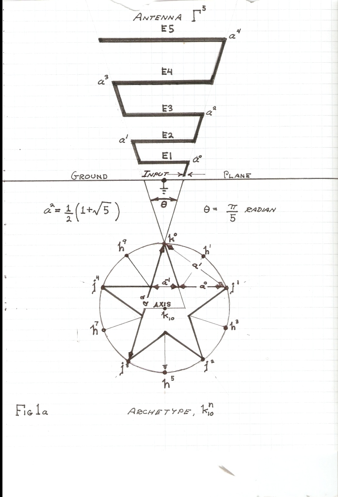
The total length of wire counter-spatially sub-divided into the log-periodic is given by the expression
 (13)
(13)

Hence the basic relations of element length and total length,
 length (14)
 length (14)
Hereby the dimensions of any lineal wire log-periodic can be determined.
The individual element lengths are each half wave sections at their fundamental frequencies This determines the actual band of operating frequencies. Higher order expressions, (a wider spand of the infinite series) give wider bandwidths of operation. In this example the width is expressed as,
 percent (15)
Within this range of frequencies the given log-periodic structure becomes a horizontally polarized electro-magnetic wave projector. This is commonly known as a broadside antenna array. In this band this log periodic structure is dimensionally a Spatial structure. Conversely, this log-periodic structure is dimensionally a counter-spatial structure when the total length,  , is
, is
 length (16)

Where it is given
c = Luminal Velocity
 = Frequency in C.P.S.
Hence this structure has both a “high broadband” T.E.M. Mode, and also a “Low Band” L.M.D. Mode with one specific operating frequency of  .
.
Break
(I) In the prior section a golden ratio log-periodic array was developed. This array can operate in two modes, a spatial mode and a counter-spatial mode. In the spatial mode the array is an electro-magnetic antenna. This mode is operative when the applied frequency is within the range of its log-periodic span. In the counter-spatial mode the array is a reactive network operating at the fundamental frequency as determined by the total wire length Lo. This mode is known as a quarter wave resonant line. Little information exists with regard to this mode of operation. Marconi utilized such arrangements to circumvent the Tesla Transformer patents. See “Vril Compendium, Aerial Radio”, by Vassilatos. Here they are called “articulated antenna.” In both the spatial and counter-spatial modes of operation this log-periodic structure is of an un-balanced, or asymmetrical form. Hence it must operate over an infinite ground plane.
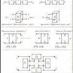
(II) The log-periodic theory can be applied to networks as well as antenna. Consider a concatenated sequence of reactive networks in a most basic form. This is the artificial transmission line as conceived by A. Kennelly, Fig (1). Each individual network,  , in the sequence is identical to the one that follows it and the one that precedes it, Fig (2). In this example the scale factor a is unity. For a log-periodic concatenated sequence of networks each individual network differs from that which follows it and that which precedes it, this by a constant numeric ratio, Fig (3). This constant is the Scale Factor, a,
 numeric (1)
Both structures can be regarded as artificial lines, but in the case of the log-periodic line, its parameters depart further from those at the input as the progression down the length of the line increases. This is to say the output bears no resemblance to the input but is transformed by the compounded scale factor,  , where N is the total number of networks in the log-periodic sequence. Thus the log-periodic line is not a transmission structure in the normal application. This suggests that rather than a transmission structure the log-periodic line is more like what is known in network theory as a Reactance Arm. See “Communication Networks” by Ernst Guillemin. Also see information on the “Guillemin Line” for radar use.
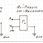
In a normal transmission structure there exists a set of input terminals and a set of output terminals, each distinct from the other. The exact number of terminals depends on the number of phases, two being common, Fig (4). For the reactance arm there is only one set of terminals which serve as both input and output. Considering this in terms of the common antenna it also has only one set of terminals, the input on transmit, or the output on receive. The other set of terminals is into, or out of, the Aether, this in accord with the Law of Reciprocity. This set of terminals can take on three distinct forms, Fig (5),
1)Bi-Phasic Balanced,
2) Bi-Phasic Un-Balanced,
3) Mono-Phasic, Direct.
Condition one is the common dipole antenna fed by a balanced two wire line,
Condition two is the A.M. Broadcast tower fed by a co-axial line,
Condition three is the Tesla Transformer directly Earthed.
Condition two is a special case of condition one and is a half antenna. The conjugate half antenna is the reflection of it by the ground plane. This is a mirror (phase opposition) image and is known as the “image antenna”. No such image exists for condition three. This is an area of the unknown but will be the beginning point for the “Bolinas Antenna”.
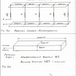
(III) Our objective is to apply the log-periodic principle to the Alexanderson multiple loaded flat top aerial structure. Ernst Alexanderson developed several antenna structures for General Electric and Radio Corporation efforts at the Bolinas Marconi-R.C.A. Station, 1920. One in particular became very well known as the Alexanderson V.L.F. Multiple loaded array. Bolinas was to have the full embodiment of the Alexanderson patents, whereas later stations were only to be partial versions as shown in Fig (6). A complete working station still stands in Sweden, call sign SAL. In Bolinas only concrete foundations remain. Fortunately the efforts of the G.G.N.R.A. axis to destroy these failed. Here is where I began my “re-awakened” study of the Alexanderson system after reading the “Vril Compendium” by Vassilatos (1998). This led to the highly developed “Landers Antenna”.
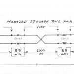
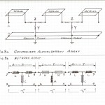
(IV) The basic Alexanderson concept can be regarded as an extension of the loaded telephone line, the path is from Heaviside to Pupin, then Campbell. This became the “Bell System”, the “8th Wonder of the World”, (not anymore). Telephone loading made the frequency response of wire lines much more uniform by correcting for the distortion introduced by the conductivity of the wires. This distortion became severe in cable circuits. The loaded telephone line is a sequential series of reactance coils and of twisted pair wire lines, Fig (7). For “Code H” toll circuit loading the complete line is made up of 19 gauge twisted pairs in spans of 6000ft length, each span is interconnected to the adjacent spans thru an 88 milli-henry set of reactance coils.
The generalized Alexanderson multiple loaded array is shown in Fig (8). Reactance arms Z and Suceptance arms Y can be of any form and here are symbolized as simple resistors for simplicity. It can be seen that the Alexanderson loading is in many ways the same as the telephone line loading. It is however the loaded cable pair is a terminated transmission line, whereas the “Alexanderson Line” is open ended, or a stub line, and thus in itself is a reactance arm with only one set of terminals. Further it is that the twisted pair has no external electric field, whereas the objective in the Alexanderson Line is a totally external electric field. This is a dielectric field carrying a displacement current. The AETHER is the output of the Alexanderson Line, whereas a TELEHONE is the output of the loaded pair. The Alexanderson system is operated in the geo-physical critical frequency band around 20 kilocycles per second, (this is in the V.L.F. Range, 3kc to 30kc). This band is a convergence between Telluric Frequencies and Atmospheric Frequencies, and it shifts days before large seismic events. See “Vril Compendium”, “Military V.L.F. Radio”, by Vassilatos. This is an important area of research. (Landers)
(V) It is little known that Ernst Alexanderson also developed high frequency, (3 megacycles to 30 megacycles), electro-magnetic antennae for the Bolinas station. Two in particular are noteworthy,
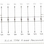
1) The R.C.A. type A wave projector, Fig (9)
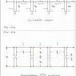
2) The Collinear Dipole Array, Fig (10)
Both antennae utilize the Alexanderson loading scheme. The type A is loaded transmission line structure and led to the R.C.A. “Fish Bone” antenna later developed by Beverage, Carter, and Hansel of R.C.A. Laboratories. For more on these R.C.A. developments see “Radio Antenna Engineering” by Laport, here are numerous photos and diagrams of the “Lost Antennae” of Bolinas.
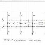
In the type A each loading section on the two wire line is a parallel connection of an electro-magnetic dipole and a shunt reactance coil. This coil is so proportioned to cancel the dielectric induction of the span of two wire line preceding it, Fig (11).
This shunt reactance “tunes out” the shunt capacitance of the line element, and thereby tunes out the Velocity of Light, the actual dimensions of the capacitance. The result is no time delay along the two wire line exciting the radiators. Propagation is now instantaneous. Hereby all the radiators operate in phase unison resulting in the type A being a broadside array with a vertical polarization. Since no standing waves are possible on a line with no propagation delay all radiators appear in parallel at the feed terminals. A 600 ohm resistive impedance results. The Type A is obviously a single frequency antenna and this is its prime defect. R.C.A. operated the A arrays at power levels of 40 to 80 kilowatts at frequencies in the H.F. point to point service.
(VI) Alexanderson also developed the co-linear array for the R.C.A. H.F. maritime mobile service (KPH). The co-linear array is an alternating sequence of half wave radiators and of phase reversing stubs. The result is that all half wave radiators operate in phase conjunction. Where it is all the radiators of the Type A are in PARALLEL, those of the co-linear are all in SERIES. Both share the PHASE UNISON CONDITION and are a concatenated sequence of networks and elements, the fundamental Alexanderson principle. The co-linear is a harmonic array and operates not only at its fundamental frequency but also at the third harmonic of that frequency. Operation on the fifth and seventh harmonics is possible but is of poor performance. There is the beginnings of a “frequency independent” antenna. This is an objective in the “Bolinas Antenna”.
The co-linear array developed into the most common antennae in use today, Fig (12). This is the co-axial vertical phased array and it has extensive application in the land mobile V.H.F. and U.H.F. Services, 30 megacycles to 1000 megacycles. With some minor changes this antenna arch-form will serve as the seed element for the “Bolinas Antenna”.
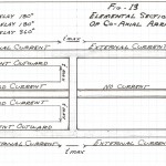
(VII) The element of the co-axial co-linear is shown in Fig (13). This element operates in two different modes at the same time. One mode is the transmission line mode, the other mode is the antenna mode. In the transmission line mode the electric field is confined to the counter-space between the element conductors, nothing gets out. In the antenna mode the electric field is spatial, external to the conductors. The external field is subject to the hysteresis of the Aether and this gives rise to a “radiation resistance”. This is discussed in “Velocity of Propagation of The Electric Field” from the 1920 Transient Phenomena book by C.P. Steinmetz.
Here exists the loading section and the line section sharing the same geometric structure. It is a dual mode transmission line. To decrease the radiation loss and increase the reactance of the co-axial element is modified to that shown in Fig (14). This will be the arch-element.
Fig (14)
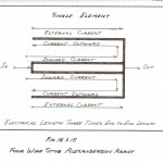
(VIII) The end to end transmission delay of this element is now three times that of an equivalent single mode section. This element is hereby three times the electrical length of a single mode section. Because only one third of the propagation path gives rise to an external electric field its radiation resistance is only one third that of a single mode section. Also the wavelength is shortened by a factor of three, and the effective end to end velocity of the element is one third the luminal velocity of the dielectric in which the element exists. Hence a concatenated sequence of these elements establishes a “slow wave” structure of reduced radiation losses. The effective wavelength is now three times that of the end to end length of the concatenated sequence. For example a sequence of N elements one twelfth wavelength end to end has an effective length of one quarter wave. Hence this “array” is well adapted to confined antenna situations. Here derived is a basic Alexanderson multiple loaded array for the high frequency band, Fig (15).
Fig (15)
Break, more to follow
DE N6KPH
Table 1, Fig (1)
19 Gauge Toll Cable Pair
2R = 88 ohm / mile
2L = 1 milli-henry / mile
2G = 5 micro-siemens / mile
2C = 0.054 micro-farad / mile
1) In sections one of the “Camp David Antenna” the log-periodic scaling factor was developed. The derived log-periodic sequence is a prelude to a more extended versor system. This leads to a complex versor operator for hyperbolic as well as circular functions. In addition the self-replicating “Golden Ratio” log base was utilized in the derivation of a physical geometric structure, a broadband broadside array.
(2) In section two the concept of sequential loading on a transmission system was developed. It was shown how Alexanderson employed sequential counter-spatial loading elements in his aerials. These are the mutual co-efficients, elastance, K, and enductance, M. This sequential loading gives a concatenated alternating series of counter-spatial and spatial elements. The pair of dimensional relations, space and counter-space, serve to neutralized each other. Hereby derived is propagating without delay. This loading configuration can be called the “Alexanderson Principle”, (space scalar). Concluding section two was the actual physical development of a linear sequential Alexanderson array, this is commonly known as a “Slow Wave” structure (0.33c). This arrangement is applicable to the high frequency band, 3 to 30 mega-cycles, as a vertical aerial.
(3) In this final section the log-periodic, the golden ratio, and the Alexanderson, principles are all united into the “Bolinas Antenna”. Also in this final section the Earth connection requirements for the telluric systems here described are given. Finally the general application of engineerable telluric transmission systems is considered. “So let the pots and pans go black and let us begin the work”. (Oliver Heaviside).
(4) The system developed by Tesla as well as the system developed by Alexanderson are both distinctly single frequency arrangements (this is what we seek to overcome). These telluric systems involve resonance or in general employ the cancellation of reactance by a conjugate suceptance. This condition can only exist at one frequency, or in some cases (Tesla), this one frequency along with its odd order harmonics. The adulteration of the Tesla system by Marconi led to very high magnification factors that prohibited high speed keying. Moreover this magnification did not contribute to the transmission process. In an effort initiated by the U.S. Navy, the Alexanderson aerial developments were applied to the Marconi aerials at station KET in Bolinas, California, and at station WII in New Brunswick, New Jersey. Thru sequential loading and subdivision of these Marconi aerials, Alexanderson redirected the energy of the aerials into the transmission process. This multiple tuned circuit configuration accordingly broadened the modulation bandwidth of the system.
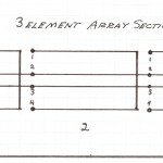
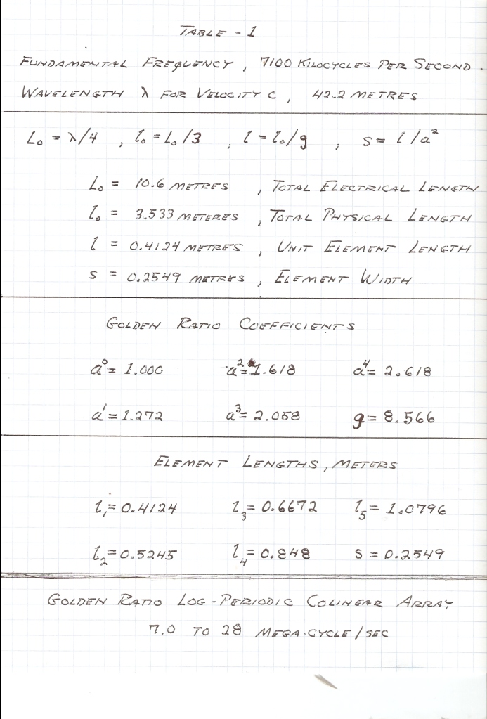
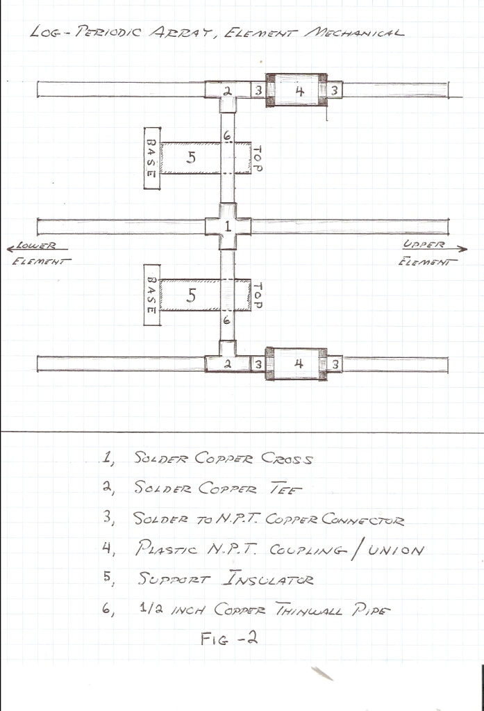
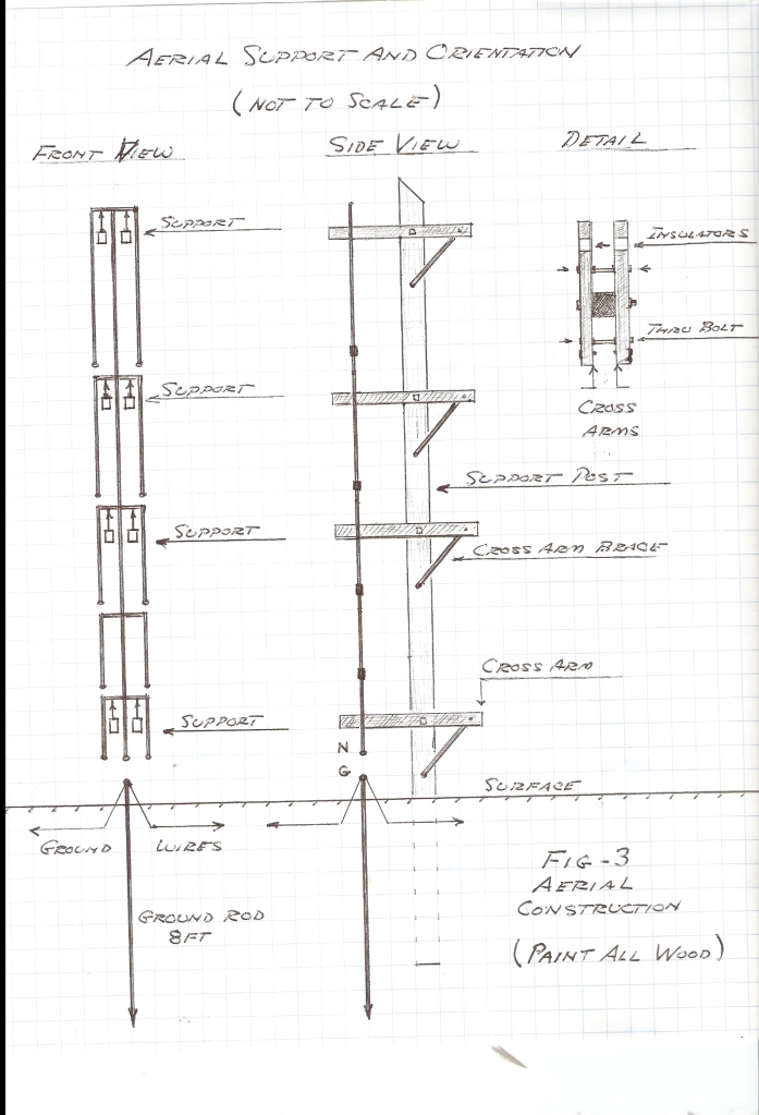
(5) Because the Alexanderson aerial is a sequentially loaded transmission network the log-periodic principle can directly be applied. The resulting structure is shown in Fig-1. This is developed for 5 logarithmic periods. In table-1 is a specific set of dimensions for operation in the high frequency band. The fundamental frequency is 7100 kilocycles per second. This aerial is a slow wave broadband vertical co-linear log-periodic array for both telluric and ionospheric applications. A suitable ground plane is required for its operation, the minimum is 80 wires in a radial configuration. Each wire is 18 gauge or larger and 20 feet or longer. (1600 feet of wire). This should be buried in a watered garden plot. The roots of plants are excellent connections to the Earth. Construction details for a “plumbing” version is shown in Figs-2&3. This is not something one is likely to see in QST magazine. The foremost application of this Aerial-Earth structure is operation in locations where height is a prohibitive restriction.
(6) The Earth connection in telluric systems is of difficult and costly construction, and here exists little room for compromise. The series impedance must be extremely low, and ohm or less. As for the Tesla system the “roots” of Wardenclyff attest to this. The Earth connection at Bolinas is 750 thousand square feet, with plates out to sea! The systems of Tesla and Alexanderson possess very low radiation resistance losses and this gives rise to very large Earth currents. These currents must find their way to the system neutral without opposition. In a complimentary manner very high potentials are developed at the conjugate aerial terminals of these telluric systems. The large currents and high potentials both serve as principle obstacle in the attainment of effective telluric transmission and reception. It should be noted there the meaning of high potentials and large currents. In a receiving system transforming one micro-watt a potential of one volt is a very high voltage and a current of one milli-ampere is a large current. If the same system is transforming 100 watts the potential is now 10 kilo-volts and the current is now 10 amperes. Therefore receiving systems are required to have a “copper investment” similar to that of a transmitting system in order to be effective in its transforming ability.
The bane of large neutral currents is any form of back E.M.F. The primary sources of back E.M.F. are resistance and reactance, giving rise to an effective SERIES IMPEDANCE, this impedance between neutral and ground. Hence a common ground rod in the dirt is no more than a series resistor, and likewise, the connecting wire is now a series reactive parasitic antenna. In common “grounding” it is indeed resistance and reactance are abundant. Moreover these only burden the neutral of the telluric transmission system. In contra-distinction, the bane of a high terminal potential is conductance and suceptance, these giving rise to an effective SHUNT ADMITTANCE. Corona, lousy insulation, and even nearby objects all act to burden the terminal potential. The suppression of spark discharges becomes a primary obstacle in situations involving considerable power. The burdens on the system give rise to detuning effects and resulting off resonance conditions.
(7) The dimensional relation of impedance is here the principle transmission impairment. This dimensional relation can hereby be neutralized thru the employment of a conjugate dimensional relation, admittance. Impedance is the versor combination of the molecular resistance in ohms and of the magnetic field reactance in Henry per second. These are the sources of back E.M.F. Admittance is the versor combination of these molecular conductance in Siemens and dielectric suceptance in farad per second. Under ideal circumstances these two dimensional relations cancel each other, this giving a node of zero E.M.F. at the system neutral. This removes the burden upon the transmission system. Here the transmission characteristics of the Earth become part of the process. Except that power due to energy transmission, this node is a point of zero power flow. (See “Impulses, Waves, and Discharges” page 114, compound circuits).
(8) From a less ideal standpoint an effective Earth connection is an admittance consisting of the molecular conductivity of water and the capacitance of large metallic surface areas. This admittance, as the parallel connection of G and B, appears in series with the impedance, R and X, to the neutral. The objective is the complete elimination of any magnetic induction or reactance. This is achieved by directing the paths of current flow normal to the surface of the metallic structures of the ground system.
Because of the difficulty and expense of constructing a suitable Earth terminal it is best to find one already in existence. Most low frequency radio navigation stations are long gone but in many locations the ground systems are still intact. These sites are optimum for the development of telluric transmission systems. It should be noted that the entire 100 Kc/sec Loran system has been recently shut down making possible the development of a naval telluric transmission system. Also there exists numerous abandoned ground systems left behind by A.M. broadcasting stations. It is possible to share existing grounds with active on air stations in some applications.
(9) Following the successful experimental efforts at Camp David in Bolinas, California the objective was thereafter the implementation of an operating telluric transmission system at the nearby R.C.A. – Marconi radio transmission facility, station KPH. KPH was a commercial ship to shore communications service. Ships in water of course are optimum Earth connections. KPH Bolinas held license to its original low frequency allocation of 126 kilocycles per second. To help facilitate this effort the Alexanderson KET grounding network was found to be intact as well as its connecting points on the still standing shunt coil bases. And further, the self resonant frequency of the Alexanderson shunt (M) coils was near to 126 Kc/sec. With these important factors in place the plan was the utilization of a replicated shunt coil standing on, and grounded to, the existing base. By the addition of a primary resonator, this shunt coil would operate as a Tesla mode resonant transformer producing strong telluric currents at the licensed frequency of 126 Kc/sec. It was a good idea but KPH was put out of operation and I was locked out by the “Greenie”S.S. Here existed one practical telluric transmission application, this as non-Maxwellian ship to shore communication. Nein!
(10) The crystal radio initiative in all probability will develop into a powerful A.M. broadcast “DX” receiving tool for which I will receive nothing. A.M. broadcasting exists on low frequency allocations in some countries, but in general the allocations are in a portion of the medium frequency band. It is important to note that the amateur radio service is allocated one medium frequency band from 1800 to 2000 Kc/sec. Here experimental A.M. telluric transmissions can take place. This could possibly lead to a commercial A.M. broadcast station.
(11) The largest kilo-volt-ampere user of telluric transmission systems is the United States Navy. This is for secure submarine communication in the very low frequency band of 20 to 30 Kc/sec. The most prominent station is in Jim Creek, Washington (State), operating near 25 Kc/sec. This station delivers 2000 kilowatts into an aerial strung between mountain peaks. This station is the epitome of the Einstein-Marconi follies, perpetuated by minds such as the Corums, T. Grotz and the I.E.E.E. Gang in general. The result is an enormous electric bill and for what, ineffective communication below the “skin depth” of sea water. Is “the group” so all mighty that even the U.S. Navy is denied the technology of Nikola Tesla?
(12) Telluric transmission systems could take many forms from hobby toys to powerful military communication systems. The properly designed system requires no energy delivery into electro-magnetic radiation losses, greatly reducing the energy requirements. Also it is that telluric currents propagate deep into the telluric medium regardless of the depth. Finally, in all probability it would be found that the attenuation & delay encountered in propagation would be very much less than those encountered in an equivalent electro-magnetic system.
It will take the works of engineers, not physicists to develop working telluric transmission systems. The physics trained engineer will be of no use, he is the enemy. Ultimately the effort falls in the lap of amateur radio. The opposition to the initiative will of course be the emerging totalitarianism of State Science (S.S.).
Herewith closes the topic of Telluric Transmission. All the required preliminary engineering material has been presented. “Tesla” societies, the American Radio Relay League, Bearden/Puharich Zealots, and P.E.E.E. trolls no longer have any meaning and any further reference to, or by them can only be considered pathological. The effort toward development will be your own initiative.
73 DE N6KPH

