Disclaimer:
In order to understand Eric Dollard and therefore Steinmetz and Tesla one must basically learn a new language…a new set of terminology. A lot of the words that conventional physicists and Electrical Engineers use have been REDEFINED by Mr.Dollard so that the vocabulary can be expanded to encompass totally new concepts and ideas. Special thanks to Garrett and Raui for helping explain some of these terms. Writing a new dictionary is complicated and I will update this page periodically when I see clear and concise explanations. This section is incomplete & a work in progress…..there may be contradictions in terms.
Glossary/Definitions:
Fields:
- Flux lines – never cross each other; they can be bunched, crowded, or thinned out over a large area. When they are bunched or crowded, each flux line has a repelling effect upon its neighboring flux line. This tends to keep them separated from one another. A flux line has tension. It can be stretched or constricted along the direction of the lines of force. This tension is somewhat like a stretched rubber band, prone to become as short as possible. (Source – Garrett M)
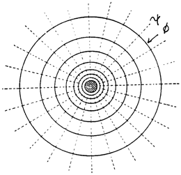
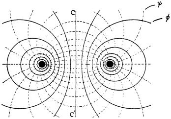
- Permittivity – The Dielectric Circuit – (Aether Constant) – The energy of an electric-field is in the space outside of the “charged body”, such as conducting wires or plates of a capacitor. Considering that all lines of dielectric force terminate on the surfaces of bounding conductors, the space between two charged bodies as the only seat of energy, then the expression “charged body” is best replaced by “terminal surface” of the field. These lines of dielectric force are directed inwards into the bounded insulating space and cause a mechanical attraction of conductor terminal surfaces.Permittivity is the concentration of dielectric flux lines a specific dielectric is capable of supporting per cross-section area. This spatial concentration of dielectric flux lines is caused by the density of dielectric dipoles, or capacity per unit area a specific dielectric material has for flux lines. The action of spatially concentrating flux lines can also be looked at as the measure of ease by which a dielectric material may permit flux lines to enter or travel through it and is an analog of conductivity in an electric circuit. (Source – Garrett M)
- —————
- Permeability – The Magnetic Circuit – (Aether Constant) – The energy of a magnetic-field is in the space outside of the current conducting medium, such as a wire or coil. The energy of this field is composed of magnetic lines of force that form closed loops upon themselves and expand outward, from their source, into space. A collective of magnetic lines forms a magnetic flux.Permeability is the concentration of magnetic flux lines, per cross-section area, a specific material is capable of supporting. This spatial concentration of magnetic flux lines is directly proportional to the density of magnetic domains a material has and inversely to its polarization or alignment of magnetic domains. The density of magnetic domains can be looked at as the capacity per unit area, a specific magnetic material has for flux lines and the magnitude of polarization as the capacity used. The action of spatially concentrating flux lines can also be looked at as the measure of ease by which a magnetic material will permit flux lines to enter or travel through it and is an analog of conductivity in an electric circuit. (Source – Garrett M)
- Inductance – Energy stored in the form of a magnetic field
- Capacitance – Energy stored in the form of dielectric field
- Self-Capacitance or Parasitic Capacitance – Capacitance between windings on an inductor
- Mutual Inductance is when voltage impressed upon one coil induces a voltage in another
- L, Leakage Inductance – Leakage inductance can only store energy it CAN NOT TRANSFER ENERGY
- M, Mutual Inductance – Magnetic energy stored in Normal Space. Mutual induction of the magnetic field is that which transfers energy in-between two separate coils, there is no storage of energy here, only the transfer of energy from one distinct coil to another.
- C, Leakage Capacitance –
- K, Mutual Capacitance – ALL DIELECTRIC ENERGY IS CONSIDERED AS A COUNTER SPATIAL ENERGY. Thus, the storage of dielectric energy is greater when there is MORE counter space for the energy to occupy. This can be looked at as the RECIPROCAL of SPACE or a “large space” divided into the “unit” (1) is an equally large “counter space”. This is seen in the design of a capacitor, the closer the plates are the more “storage” or “capacity” the capacitor has, it’s that simple. K is when there are multiple C’s that are mutual with one another, or MULTIPLE separate metallic surfaces linked via dielectric flux, this in the secondary is seen in-between turns.
- Induction – can be Electro-Magnetic OR Dielectric/Electrostatic
- Magnetic Reluctance – how much current can be sustained with flux; also known as “magnetic resistance”; stores energy in magnetic field instead of dissipating; units: are inverse Henries, H–1
- Impedance – lines of flux you can sustain to create current
Resistances:
- Resistance – Measured in Ohms
- Reactance – Measured in Ohms
- Inductive Reactance – resits a change in current (such as a inductor)
- Capacitive Reactance – resists a change in voltage (such as a capacitor)
- Impedance – measure of opposition/Resistance in a conductor in Z (ohms); 4 Forms – 1.Natural 2.Characteristic 3. Surge 4. Load
- Elastance – variation of resistance with respect to time in per Farad
- Negative Resistance created by two conditions
- Decreasing Inductance
- Deceasing Capacitance
Ease of flow:
- Conductance – The inverse of resistance
- Admittance – measure of ease of current flow in Y; the inverse of impedance
- Enductance – variation of conductance with respect to time results in per Henry
Energy, Work & Powers:
- Energy – in a system; measured in joules or planks per second
- Work – the change of energy in a system; also measured in joules or planks per second
- Power – the work per second; measured in Watts or Joules per second or Planck’s per second per second; rate of disspation
- True, Reactive and Apparent Power
Waves:
- Longitudinal Wave – Animation
- Standing Waves – zones of constructive and destructive interference on a line; represent the storage of energy, in Magnetic and Dielectric Form, by the Electric Field of the Transmission Line. This again represents a condition of left over Lines of Force. This is to say, not all Magnetic Lines of Force are united with all Dielectric Lines of Force. The left over Lines of Force represent Stored Energy. This stored energy gives rise to physical forces upon the conductors of the Transmission Line. It can be reasoned that these physical forces upon the Line Conductors are the result of Standing Waves on the Transmission Line. Standing Waves give rise to Stored Energy in the Electric Field of the Line, this resulting in physical forces upon the Line Conductors. The Transmission Line can act both as a Magnetic Inductance, and as a Dielectric Capacitance. One section of Line may exhibit a Magnetic excess and thus behave as an Inductance, and another section of Line may exhibit a Dielectric excess, and thus behave as a Capacitance. The effect of standing waves is to separate the Magnetic Induction and the Dielectric Induction in space along the length of the Transmission Line. Hereby differing physical forces act in a differing manner upon different sections along the length of the Line. (Animation)
- Tank Circuit (Electromagnetic Oscillating Circuit) – Animation
- Resonance – In physics, resonance is the tendency of a system to oscillate at a greater amplitude at some frequencies than at others. These are known as the system’s resonant frequencies (or resonance frequencies). At these frequencies, even small periodic driving forces can produce large amplitude oscillations, because the system stores vibrational energy.
- Octave
- Oscillation
- Heterodyne
- Phase Conjugation
- Frequency
- Consonant
- Melody
- Rhythm
- Caduceus
- Harmonics
- Electronic Oscillator
Other:
- Reactive
- Versor – Wikipedia
- Quaternion – Wikipedia
- Parametric Oscillator – Wikipedia
- Counterspace – on Borderland Research on nct.anth
- Waveguide
- MKS
- Poynting Vector
- Litz Wire & Bifilar Coil
- Distributed element model – In electrical engineering, the distributed element model or transmission line model of electrical circuits assumes that the attributes of the circuit (resistance, capacitance, and inductance) are distributed continuously throughout the material of the circuit. This is in contrast to the more common lumped element model, which assumes that these values are lumped into electrical components that are joined by perfectly conducting wires. In the distributed element model, each circuit element is infinitesimally small, and the wires connecting elements are not assumed to be perfect conductors; that is, they have impedance. Unlike the lumped element model, it assumes non-uniform current along each branch and non-uniform voltage along each node. The distributed model is used at high frequencies where the wavelength approaches the physical dimensions of the circuit, making the lumped model inaccurate.
- Lumped element model
Terms & Symbols:
- Ψ = Psi; Dielectric Induction
- Φ = Phi; Magnetic Induction
- Q = The Planck; Unit of Electrification; (can be called a photon?)
- e = Electro-Static Potential/Volts
- I = Ampere Current Displacement
- E = Electro-Motive Force
- i = Conduction Current; Magneto-Motive Force (M.M.F.)
- μ = Mu; Permeability (Magnetic)
- ε = Epsilon; Permittivity (Dielectric)
- R = resistance in Ohms
- G = conductance in Siemens
- X = reactance in Henrys per second
- B = susceptance in Farads per second
- L = Self Inductance; magnetic repulsion in Henry; Webers/Amperes; Storage in Space
- C = Self Capacitance; dielectric attraction in Farad; Storage in Space
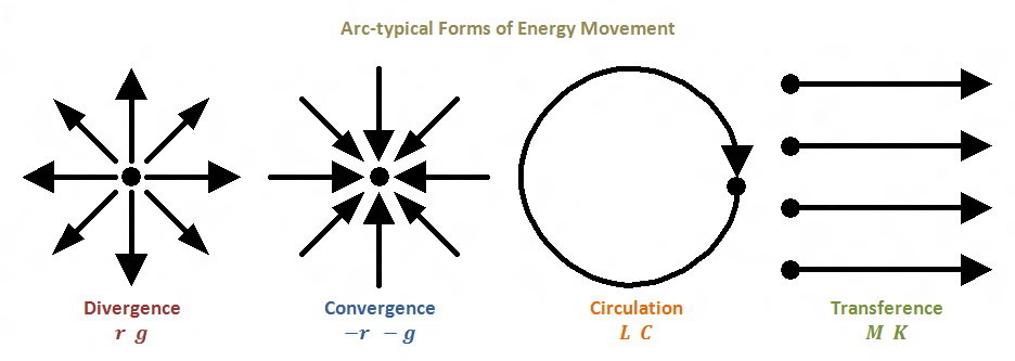
- M = Mutual Inductance/Enduction; magnetic attraction in Per Henry; Amperes/Webers; 1/L; Transfer energy via Counterspace pathway
- K = Mutual Elastance/Enductance; dielectric repulsion in Per Farad; 1/C; Transfer energy via Counterspace pathway
Formulas/Relationships:
- Q = Ψ x Φ
- Z(surge impedance) = √(L/C)
- Z(natural impedance) = √(L/C)
- LM is called the Magnetic Space Factor – Henry per Henry
- CK is called the Dielectric Space Factor – Farad per Farad
- LC represents the Transverse Electro-Magnetic wave
- MK represents the Longitudinal Magneto-Dielectric Wave
- The time function of LC, dt=(Square Root of (LC))
- The time function of MK, dt=(Square Root of (1/MK))
- The time function of LK, dt=(Square Root of (L/K))
- The time function of MC, dt=(Square Root of (C/M))
- TE – Transverse Electric (Dielectric)
- TM – Transverse Magnetic
- TEM – Transverse Electro-magnetic
- LD – Longitudinal Dielectric
- LM – Longitudinal Magneto
- LMD – Longitudinal magneto Dielectric
- AC is a 2-D representation of an actual 3-D double helix
- The AC sine wave wrapped around itself is an Ellipse! (real trig is an ellipse NOT a circle)
- Longitudinal wave is a spiral disturbance (debatable)
Notes from Principles of Wireless Energy – Audio Clip
The TMT involves 3 distinct Standing Electric Waves
- The Electric Wave in the Earth – Space Dimensional
- The Electric Wave of the LC oscillation – Time Dimensional
- The grounding System a new kind of wave – Extra Dimensional (Tesla calls it ‘extra coil’)
Music Analogue
- Harmony is Space Dimensional
- Rhythm is Time Dimensional
- Melody Is Extra Dimensional
J.S.Bach fundamental expression of electricity beyond Steimetz
Triple Energy Transient
3 standing Waves each containing a pair of energy -> 6 forms of energy
not just regular resonance………..but consonant resonance <—-
Energy vs. Power:
“Quote:
|
3) Discontinue the practice of habitually exchanging the terms power and energy as if they are equivalent, they are not. Engines are not motors, etc.
|
For anyone who doesn’t quite understand this. Energy maybe conserved but theoretically we can derive an almost infinite power from small amount of energy, remember that it is power that turns out motors, lights our lightbulbs etc etc. Time is where our energy comes from and our circuits are powered by time (in a sense atleast).
For example;
Say we change a systems energy by one joule. That statement means absolutely nothing without a time factor. If we change the energy by 1 joule per second we have 1 watt, not a very powerful exchange. However if we moved 1 joule in a 10th of a second our result is; 1/0.1 = 10W or perhaps even 100th of a second; 1/0.01 = 100W and just incase you haven’t caught yet consider 1 thousandth of a second; 1/0.001 = 1000W or 1kW
So you can see that in every joule of energy is the ability to do deliver many watts in our circuit, the factor of consideration is not so much how many energy can be derived from a system but the speed of this exchange which is what we should exploit.
Raui” ~ source
Energy, Work and Power: (Explained by Raui)
I thought I’d pop in and give my two cents on this whole energy, work and power debate, it’s application to power magnification and to help clear up a few things which have been asked. This is just a summary of my current understanding which may or may not be able to help those concerned come to a further understanding of what Eric is trying to say.
First of all we’ll go back to our fundamental dimensional relations of the difference between energy, work and power. Energy measured is measured in joules, or plancks per second where the Planck was defined by Eric as being of dimensions joule-seconds. Energy is an implied quantity which is only of interest when conditions in a system are changing. If something in our universe changes in any way energy must be equally exchanged between it’s various forms (electromagnetic, kinetic, etc.) as to remain a constant quantity as per the Law of the Conservation of Energy or for the Mr Heaviside’s out there – ‘The Law of the Continuity of Energy’.
When something changes and energy is exchanged there are two more quantities we can talk about and they are work and power. Work is also measured in Joules and is the difference in the energy magnitude from before the system changed to after the system changed. It should be noted that here we have 2 quantities, being energy and work, which have the same dimesions of Joules but represent two slightly different things which is a theme which pops up in the work of Mr Dollard (E,e,I,i being an example).
Power is measured in Watts, Joules per second or Plancks per second per second as per Dollard’s units. Power and work are very closely related in that power is measured as the work per second. So basically when the level of energy changes within a system the magnitude of the change is the work and the rapidity of the change is the power.
Okay now let’s apply our now defined quantities into a practical situation – the charging and discharging of a capacitor. Let’s say I have a 12v battery and I want to charge a 1 Farad capacitor and I am going to charge it through a 1k ohm resistor. The energy stored within a capacitor is given by;
1.
So, from the above equation, after we charge the capacitor we can conclude that we have 72 Joules of energy stored in the dielectric field of the capacitor. The work done in charging this capacitor is given by;
2.
Since we started off with a totally uncharged capacitor (v=0 so E=0) we have done 72-0=72 Joules of work. It should be noted that if the capacitor was charged to any non-zero voltage our values of work and energy wouldn’t be equal and so here we have a case of two quantities with the same dimensions having two different meanings for if they had the same meaning they would be equivilent at all times.
So now we want to know how much power or activity we just caused from our charging. Our formula for power is given by;
3.
We already know our work (72 joules) but how much time elapsed in charging our capacitor? Luckily know that the time to charge/discharge a capacitor through a resistance r to just over 63% of it’s final value is given by;
4.
I will not try to prove this as it can easily be googled by the time for it to be charged, practically that is since theoretically it is never exactly 12v, is given by 5 times our time constant and so the time taken to charge or discharge our capacitor is given by;
5.
Therefore combining equation 1,2,3 and 5 we get;
6. 
So in charging our capacitor of 1 Farad through a 1k resistor to 12 volts we get 0.0144 Watts of electrical activity. Now let’s disconnect but not discharge the capacitor and connect it to a separate circuit so that the capacitor discharges into a 10 ohm resistor. Plugging 10 ohms into equation 6 gives 1.44 Watts discharge. The energy stored in the capacitor on charging is the same amount of energy released by the capacitor on discharging, use the above equations to prove this for yourself if don’t wish to take my word for it.
Articles:
Introduction to Dielectricity and Capacitance by Eric Dollard (on borderlands)
The Fallacy of Conductors by Eric Dollard (on borderlands)
Magnet.fsu.edu – Good source for understanding Electricity basics
People (Timeline):
- Michael Faraday (1791 – 1867)
- Gustave Le Bon (1841-1931)
- Sir Oliver Lodge (1851-1940)
- Nikola Tesla (1856-1943)
- Charles Proteus Steinmetz (1865-1923)
- Eric Dollard (1952- )
- Gerry Vassilatos
————————————–
Madhatter recap:
“I’ll utilize an analogy to help explain what Eric is talking about. the Insulator Psi and the Conductor Phi.
If I ‘shocked’ you using a condenser (capacitor) then the electro-static volts would be e and the ampere current displacement would be I.
If I did the same using a magnetic generator then the electro-motive volts would E and the conduction current is i.”
Illustrations by Garrett
Waves:
- Transverse waves – Standard electromagnetic Waves, Perpendicular waves, 90 degree phase
- Longitudinal Waves – longitudinal magneto dielectric waves… propagate radially, 0 degree phase
Electricity is comprised of two components
- Dielectricity – Generated by a capacitor, counter-space phenomena; storage and return of dielectric energy
- Magnetism –Generated by a coil of wire, decaying electricity, spatial phenomena; storage and return of magnetic energy; electro-motor force; lines per second
- Electromagnetic induction – Time & Magnetism; produces melting; retardation
- Dielectric Induction – Brighter light, no melting, higher frequency, less power usage, blue spark, living side, growth
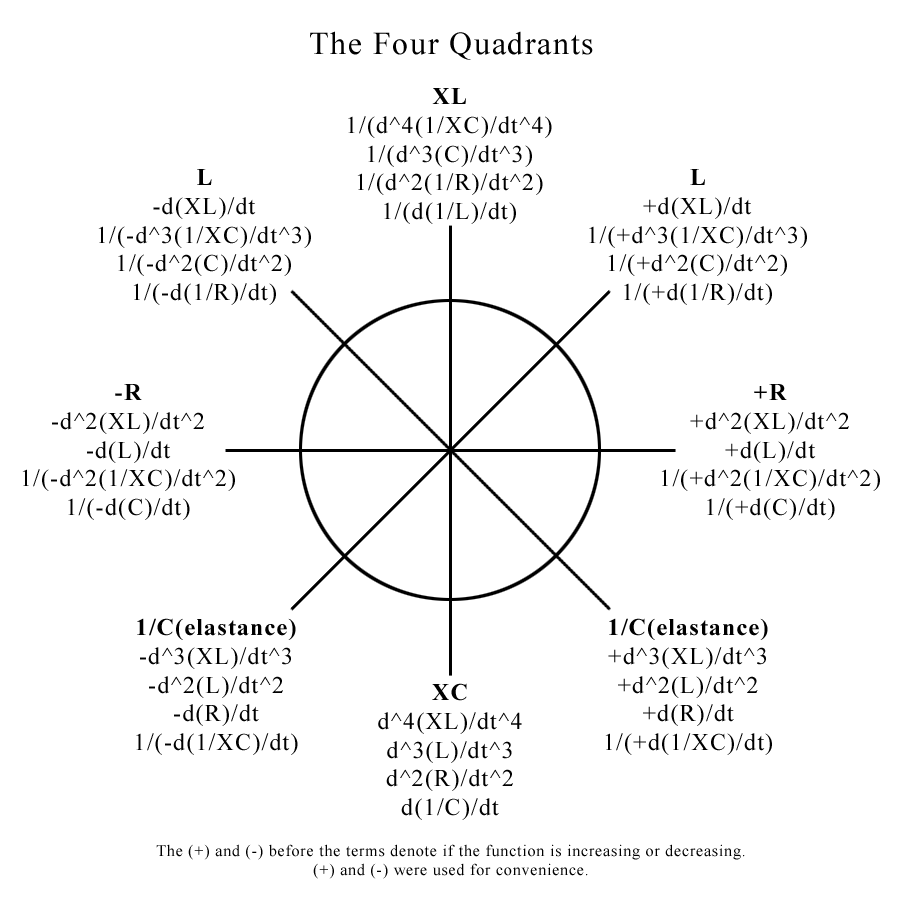
Four Quadrant Layout by Tao
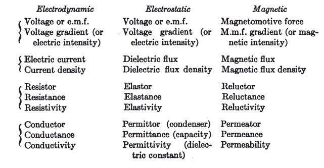
Mr. Vladimir Karapetoff, “Electric Circuit 2nd Ed [1912] – (post by Garrett)
Raui Notes on Parametric Excitation:
A changing dielectric flux = displacement current or dielectric induction
A changing magnetic flux = magnetic induction
A change of capacitance (lower -> higher) = positive conductance
A change of capacitance (higher -> lower) = negative conductance
A change of inductance (lower -> higher) = positive resistance
A change of inductance (higher -> lower) = negative resistance
So the aim of our game is to change the parameters of our circuit as quickly as we can to create/cohere energy and if this energy gain is higher than the resistive losses plus the energy required to change the parameter we have excess energy we can use to power a load!
“An effective way of capacitance changing can be by alternating between series and parallel configuration of a bank of capacitors.”
Dave Webster “The dielectric lines of force, Psi, are dragging along the conductor as they fill in the dielectric of the capacitor. The dragging of Psi/second along the wires connected to the capacitor causes a displacement current which produces magnetism.”
Key Points from Eric Dollard:
“Electricity has to be viewed from a four quadrant type of situation. The right angle plays an extremely fundamental role in electricity. It is generically a right angle phenomenon. ”
“Forget about f*ck*ng electrons. J.J. Thompson says that a hydrogen atom
has 1000 electrons, we say 1 electron, what do you know about them,
nothing. Go read and learn before parroting. Find Sir William Crookes’ work.”
“No velocity of light when coil oscillates. How many times must I repeat,
NO VELOCITY OF LIGHT. Read Tesla Colorado book, do the math on the
“extra coil.” Find that it is 1.8 times light. Read! Yes, harmonic
oscillations in coil windings generate parametric dielectric energy
storage co-efficients. Farads per second. Good path to follow.”
In my mind parameter variation at the second harmonic represents power
but parameter variation at the third harmonic represents energy. These
are just ideas, see Steimetz A.C. Theory book in his parameter variation
chapters. The magnetic amplifier of E.F.W. Alanderson is definitely the
way to go. – source
“This is the main flaw in Einstein’s
theories, and the point I am hammering through on the forum. Space and
time exist in our minds.” – source
“Stay with Centimeter, Gram, Second (CGS) units. All of my work, Tesla’s
work and Steinmetz’s work is in CGS units.
Use only the symbols that myself or Steinmetz present such as Psi, for
dielectric induction, otherwise everything will be incomprehensible.” – source
“Electricity can travel through time, but this is not to say that we can,
but it does present itself as a possibility of a time television. It has
been noticed in anomalous occurrances that radio and TV signals have
been received years after they have been broadcasted. I do not buy the
“bouncing around in space” theory, but rather a process similar to the
integratron in the form of a parasitic oscillation that the signals were
transmitted through time. This is a very intgeresting topic.
Time and space are “throw-away” wrappers which convenience of store
clerks and accountants, so-to-speak. This is the main flaw in Einstein’s
theories, and the point I am hammering through on the forum. Space and
time exist in our minds.” – source
“The exact same condition exists today with regard to radio and the more generalized wireless, except with a less favorable outcome. As shown by the Heaviside in his electrical equations and further developed by myself in the tradition of Steinmetz, wireless transmission can be shown to involve a conjugate pair of propagations, the electromagnetic and the magneto-dielectric. Electro-magnetism and the adulteration of its theories by Einstein and the like has become the accepted element of the propagation of electric forces. The conjugate magneto—dielectricity, and the brilliant presentation of its dimensionality by Rudolf Steiner and his followers is denied by the corporate cable institutes. But, as with the cable long distance case, electricity plays no favorites, and radio transmission suffers from analogous distortions. The archetype of conjugate pairs exists everywhere, however, and some examples will illustrate.
A very simple analog is the male and female of a given species. The species can only propagate as a conjugate pair, the male being the dielectric and the female the magnetic. Likewise, the branch and root of a plant work together as a conjugate pair, the sunlit branch as the magnetic and the root in darkness as the dielectric. An excellent example in symbolic representation is the final choral movement of G.F. Handel’s Alexanders Feast- “The Power of Music.”” – source
“Every electron is a motional terminus of a quantity of dielectric lines of force, these lines contracting and stretching like rubber bands, giving motion to the terminus electron. The thermionic electron contracts, pulling the electron, the cathode ray stretching, pulled by the electron. In the former case the lines of force are dissipated, in the latter case the line of force are projected, both cases the electrons assume ray like motion, with non participating lines of force filling the voids, directing the electrons. Hence, it is the electrons travel in straight lines, that is, rays.” ~ Source
“Thomson developed the “Aether Atom” ideas of M. Faraday into his “Electronic Corpuscle”, this the indivisible unit. One corpuscle terminate one one Faradic tube of force, and this quantified as one Coulomb. This corpuscle is NOT and electron, it is a constituent of what today is known as an electron. (Thomson relates 1000 corpuscles per electron) In this view, that taken by W. Crookes, J.J. Thomson, and N. Tesla, the cathode ray is not electrons, but in actuality corpuscles of the Aether. ” ~ Source
“Magnetic Inductance is thus a dimensional relation for the magnetic properties of the Aether, and Dielectric Capacitance is thus a dimensional relation for the dielectric properties of the Aether. Inductance and Capacitance are thus the application of metrical dimensional relations to certain characteristics of the Aether.
For the magnetic induction the Aetheric relation is known as the magnetic “Permeability”, for the dielectric induction the Aetheric relation is known as the dielectric “Permittivity”. These two terms were so named by Oliver Heaviside. Here the Permeability is denoted as Mu, the Permittivity as Epsilon. These two relations represent the “Magnetic Inductivity” and the “Dielectric Inductivity”, respectively. This pair of dimensional relations, Mu and Epsilon, in conjunction with the metrical dimensional relations defined by the metallic-dielectric geometry bounding the electrified Aether, constitute the dimensional relations of Inductance and Capacitance. It is therefore the Inductance and the Capacitance, L and C are in, and of, themselves metrical dimensional relations. They consist of not substancive dimensions, they are not substantial, they are metrical.
The substancive dimensional relation of Dielectric Induction, psi, in Coulomb, is combined with the metrical relation of Capacitance, C, in Farad, giving rise to the compound dimensional relation of electro-static potential, e, in Volt.” ~ Source
“The permittivity, as a factor of Capacitance, and the Permeability as a factor of Inductance represent aspects of the medium bounded by the metallic-dielectric geometry. Mu represents the magnetic aspect, Epsilon the dielectric aspect of this medium, be it Aether or 10-C oil. ” ~ Source
” Tesla was involved in a court case where he was fighting for the survival of his Wardenclyffe tower. The details of that court case were recently published by a person by the name of Leyland Anderson who apparently is a competent electrical engineer. And when you read through this you see Tesla say over, and over, and over again that his radio was “non-electromagnetic”…. Repeatedly … but it all fell on deaf ears. Once physicists grabbed hold of electricity, all knowledge of it ceased. Electrons have nothing to do with the flow of electricity; electrons are the rate at which electricity is destroyed. Electrons are the resistance. The waveform of electron flow is the same waveform produced when you slam on the brakes and hear that horrible screeching sound. It’s not a nice harmonic sine wave it’s a very bitter horrible sound of energy dissipation and material flying everywhere. Electricity flows in the space between the wires. This has always been known by Electrical engineers. For example you short out a major electrical circuit you will see the cables violently repel each other as the electromagnetic force tries to escape from the boundaries in which they are contained between the so called bounding conductors. But most people are not electrical engineers and don’t deal with the situation. I have to deal with it every day, I had a welder run away on me at work a couple of days ago every wire and every conduit tried to escape the conduit. The noise was horrible everything repelled everything rattled all the lights flashed and all the computers failed … I love it! ……. I have a little device in my car where I operate my 24v military field radios off 12v. A very crude device, it consists of a vibrator which charges two 12v capacitors in parallel at 12v and discharges them in series on 24v. If the dwell angle on the contacts in the vibrator get screwy, when you turn the switch off the thing just sits there and keeps humming, powering the 327 pilot lamp for a period of about 2 minutes. But of course, that’s impossible, it’s like all Tesla’s work, it’s all impossible. It’s like the transformer; it’s why the lights should go out right now but their still humming away.”
““The Cosmic Induction Generator”
The tesla coils are monopolar electric devices and operating two of them back to back
Tesla used coils that had a width that equalled the height
He used FLAT coils…not these modern round inductor style” ~Source (Dollard free energy video)
Free Energy a “Side-Effect” of this research – The Science of Electricity
Free Electricity – Rotating Apparatus, Or Energy Multiplication Vacuum Tubes
Specific Experimental Verification of Free Energy from Vacuum Tubes – Farnsworth did this Twice
1. Once with the Multipactor Tube – Oscillaitng Diode with Cold Cathodes & secondary emissonary material, oscillations kept going until the tube burned out (did not decay as should have)
2. Nuclear Fusion – purely electronic


