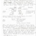
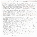
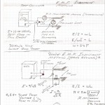
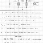
The Planck is the quantity of electrification, Q. The Einsteiner calls this a photon, and says that a Planck is the time integral of energy, W, in Joules. These relations are demonstrated in these writings and also represent the established engineering theories. Nothing is new.The Planck, Q, is the union of dielectricity, Psi, and the magnetism, Phi. These two inductions, Psi and Phi give birth to, Q, the electrification, in a transverse electro-magnetic configuration.In Heaviside/Poynting reasoning it is:
V Psi Phi, equals QThat simple, Maxwell would have loved it, but he died too soon.Physicists like three dimensions, the reason is hidden away somewhere.
(1) Mass, m
(2) Space, l
(3) Time, t
“The three” However for the electrical engineer, who is an engineer of electric power, P, in KiloWatts, or Kilo-Volt-Ampere reactive, he has no interest in mass. Therefore “The Three” become:
(1) Electrification, Q
(2) Space, l
(3) Time, t
And for the physicist:
Q equals the time integral of the shrine itself,
W= mc squared
Hence,Q, equals Wt
How simple, get the “Monsters from the Id” out of your head. No mystic secrets, just basic high school algebra. But it would make no sense to someone from the DMV.
In a more primary dimensional expression, the Planck divorces into a pair of primary dimensions, the dielectric induction, and the magnetic induction. Thus the Planck in itself is not a primary dimension, but serves as a primary dimensional relation, for the materialist.
Taken from C.P. Steinmetz in “Impulses, Waves, and Discharges”, are three dimensional conditions:
(1) The magnetic field, Phi
(2) The dielectric field, Psi
(3) The electric field, Q
When Steinmetz uses the term “Electrical Field” this is defined by Q. The Dielectric field is NOT… the electric field. Is the dead horse dead yet?
Q, in Planck is
NOT EQUAL TO
Psi, in Coulomb.
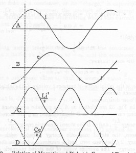
And, E equals mc squared times t equals Q. The materialistic expression to pacify the physicist. If Phi, or Psi is zero, then Q is zero. It is that Q is the PRODUCT of Psi and Phi. Both Psi and Phi must be present in order to have any Electrification, Q. Hence Q is a double frequency term that is maximum when the dielectric energy content is equal to the magnetic energy content.
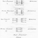
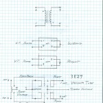
See figure in the following post
Epilogue, the Planck is not a quantum mystical myriad of Queeks and Quarks, it is a fundamental relation in both physics and electrical engineering terms. Keep the Quarks out of the Condensers, the engineer says. On the other hand, for the Quantic minded, how complex can you make a crystal set? What if Einstein says it cannot work? It is a bottomless pit.
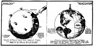
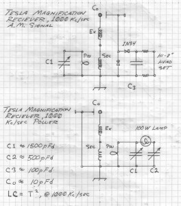
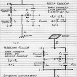
Hence it can be seen that a pair of waves are engendered by this transmission system. (Tower and Star Radials). One wave, Hertzian, is the over ground wave, the other wave, Telluric, is the under ground wave. These two waves arrive at the point of reception in their own distinct time frames, giving rise to a difference in phase. Hence, multiple rings of interference patterns are produced. Since the Hertzian portion, over ground, time frame is based upon the velocity of light, then the Telluric portion, under ground, time frame gives the Telluric velocity. Two crystal sets, one over ground, one under ground, and a basic oscilloscope , that simple. I have done this at Landers.Concluding, a Tesla Magnification Transformer, properly proportioned can, in theory, actually draw power from a local 50 kW station. Several hundred watts of power reception is likely. This would prove Tesla once and for all. No antenna, just a good ground, and a nice and bright 100 watt light bulb.This would overturn physics more than any billion dollar C.E.R.N. project. A ham radio operator overturns Einstein for 100 bucks. What a concept.
Read,
Tesla, “The True Wireless”
Tesla, “System of Concatenated Tuned Circuits”
Dollard, “System for the Transmission and Reception of Telluric Electric Waves”
A.R.R.L. “Radio Amatuers Handbook”. Chapter “H.F. Transmitters, & Tank Circuits”
73 DE N6 KPH
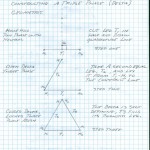
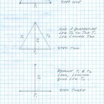
(1) It is common belief that Tesla “invented three phase” A.C. power. This belief is wrong. Tesla envisioned poly phase power quadrapolar, relating to Goethe, the sunset and the archetype called the solar cross. This is is consistant in all Native American art forms. We have four seasons, or now, four phases, just like the moon.
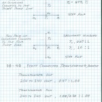
(2) The decision to employ the “Tesla System” for use in the Niagra Power Project resulted in the installation of Tesla four phase alternators, these constructed by Westinghouse Electric Co. It came to pass however that the transmission line from Niagra to Buffalo was a three phase line (11 kV) constructed by General Electric Co, the Steinmetz company. In order to interconnect the four phase system with the three phase system, a special transformer bank was developed. Westinghouse engineer, and Tesla’s co-worker, Charles Scott. This gave birth to what to what is known as the Scott Connection and is widely utilized.
(3) The theory of phases involves the theory of number systems. Recently the number systems of protocultures such as the Chaldean system was touched upon. Let us use it as an example of a number system. The Chaldean system is a base 9 number system, and its poly phase diagram is an equal-lateral nine sided polygon. Its symbolic expression is the ninth root of positive one, and it’s versor operator is k, of base nine and raised to the n power. Thus the Chaldean system is expressed by n:
0, 3, 6,
1, 4, 7,
2, 5, 8,and nine equals zero. In the related Kabalistic system it is:
1, 4, 7,
2, 5, 8,
3, 6, 9,
It is not a versor system. In genereal the nth root of one is one to the one over nth power.
Hence the table:
1) Monophase, one over one power
2) Two phase, one half power
3) Three phase, one third power
4) Four phase, one fourth power
5) Five phase, one fifth power
6) Six phase, one sixth power
…..
10) Ten phase, one tenth powerAnd ten phase is our basic Arabic number system:
0, 5,
1, 6,
2, 7,
3, 8,
4, 9,
And of course two phase is binary:0, 1
(4) If the power system has a neutral, or “Electrical Center of Gravity.” This system has one more wire than those used as phases. Hence for two phase like into your house, (mind virus – it is not single phase, single phaseis the Tesla one wire system) the 240 Volt phase pair is split into 120 V/120 V, and the two wire system has three wires. Likewise for a three phase system with a neutral there exists four wires at 120 V and now instead of 240 Volt the line voltage is 208 Volt. The square root of three is the factor. More wires than phases is best avoided, but has becom fashionable today in most electrical systems. But it has come to pass that today’s electrical systems have become problematic and also unsafe because of the improper use of neutrals.
(5) It is a consequence of multiwire T.E.M. transmission systemes that a number of conductors greater than the number of phases gives rise to parasitic modes. In telephone work they are called longitudinal currents, in audio they are called common mode currents, in power, zero sequence currents, and in radio, antenna currents. They are undesirable in all but the Tesla monophasic or one wire transmission system. Here the neutral is the neutral is the only wire.
(6) In these n plus one systems with neutrals, for a balanced non linear load (flourescent lamps, and switching power units, etc) the neutral current is not zero but consists of a harmonic system of currents. The order of harmonics is based upon the number of phases:
One phase, F
Two Phase, 2F, 4F, 6F, …
Three Phase, 3F, 6F, 9F, …
Four Phase, 4F, 8F, 12F, …
Hence considerable kVAR harmonic power can develop in neutral bearing power systems. Further, the harmonic currents are all in phase, or flow all in the same direction in the phase conductors. This gives rise to undesired E.M. radiation from the electrical system. But this is the system of today.
(7) Take for example a three phase motor, 60 cycles per second. The rotation is clockwise for 60 cps.
60, clockwise force
120, counterclockwise force
180, longitudinal, zero force
240, clockwise force
300, counter-clockwise force
360, longitudinal, no force
Hence, it is seen that harmonics cause conflicting torques in polyphase A.C. motors. And the zero sequence waveform is:
180 @ one third 1F amplitude
360 @ one sixth 1F amplitude
540 @ one ninth 1F amplitude
Etc @ one nth 1F amplitude
Try graphing this function so we can see a triplen harmonic wave like the one infecting the “Grid”
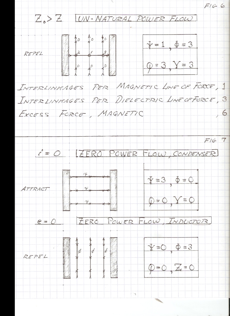
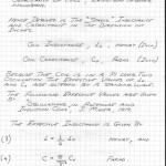
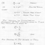
Thus by Ohm’s Law, e over i equals Z, in Ohms. Hence the Neutral Condition is expressed as an Impedance and this condition will result from this impedance having a specific value, that is, a defined ratio of e to i. This is our “Magic Number”.Based upon reasoning developed in the prior discussion of this subject, for the Neutral Condition, the ratio of the potential, e, in Volts, to the M.M.F., i, in Amperes, is numerically equal to the Natural Impedance of the line. This has yet to be proven, but the mathematical reasoning thus far leads toward this conclusion. It makes sense from an Intuitive Level, so this path will be followed. The lingering complication surrounds the use of the Aether Constants, the Permeability, Mu, and the Permittivity, Epsilon. Here seems to be where all electrical theories fall short of a concrete definition. This situation was seen in the analog of Inductance and Capacitance as a “Car Dynamic”, and the use of pounds per square inch.It can be derived that the Natural Impedance of the line gives rise to a natural ratio of Magnetic Induction, Phi, and Dielectric Induction, Psi, these throughout the line supporting the Electric Field. This again brings us back to the unit of Electrification, Q, or the Planck. It may be inferred that the Neutral Condition, a condition derived from the ratio of Inductance to Capacitance, that every Magnetic Line of Force, and every Dielectric Line of Force, are each united into a unit of Electrification, or a Planck. There are those that would call this union a “Photon”.
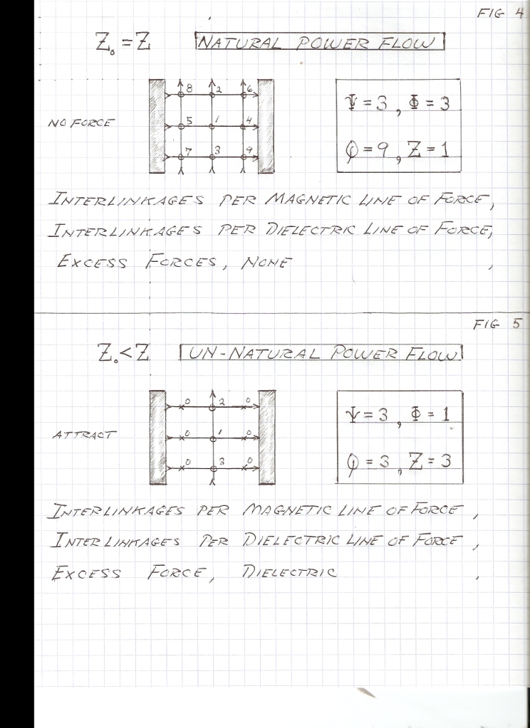
All Magnetic Lines are united with all Dielectric Lines, no Magnetic Lines, nor Dielectric Lines are left over. Here, in this condition, the Magnetic Field and the Dielectric Field perfectly mesh together into the Electrification. In this condition the flow of the Electrification is matched to the character of the transmission line thru which it is propagated. Hence the Natural Impedance of the Line is also its Characteristic Impedance.When the flow of Electrification is not matched to the Transmission Line which is propagating it, a condition of unbalance is produced. There exists an excess of Magnetic Lines of Force, or excess of Dielectric Lines of Force, not all are united into Plancks. An excess of Magnetic Induction gives rise to stored energy in this induction. This results in the Transmission Line acting as an Inductance to the Propagation of the Electric Field. Likewise, an excess of Dielectric Induction gives rise to stored energy in this induction. This is to say, a mismatched, or unbalanced, condition in the flow of Electrification thru a transmission line gives rise to the line acting as an Inductor, or Capacitor, as well as its propagation of Electrification. In the limiting case the shorted line is an Inductor, and the open line is a Condenser. Here the flow of Electrification is zero, or canceled out.
The condition of neutral force is a condition of the Impedance in the flow of Electrification. If this flow matches the Natural Impedance of the Transmission Line, the condition of equal and opposite forces exists. Hence a condition of mismatch must give rise to forces acting upon the conductors of the Transmission Line. It can be reasoned that when forces appear the conductors of the line, the flow of Electrification is not matched to the line thru which it is propagating. It may be said that it is a “Forced Fit”, and therefore forces appear as a strain upon the Forced Fitted Transmission Line. These forces upon the conductors can be equated to an excess of Magnetic, or Dielectric, Energy bound by the Transmission Line. This stored energy gives rise to physical forces upon the conductors of the Transmission Line. These forces can reach destructive magnitudes during fault current conditions.The Natural, or Characteristic, Impedance of the Transmission Line can also be equated with the Natural Power of the Line. Consider a Transmission Line with no distant end, and Infinite Line. Because of the Finite Velocity of Propagation, it’s sending end never sees the non existent distant end.
Hereby Power can be supplied to this Infinite Line Indefinitely, forever. Connecting such a Line to a source of constant potential gives rise to a traveling wave, this wave charging the Line on its way to the non existent end of the line. See Heaviside, “E.M. Theory”, “Plane Electro-Magnetic Waves”. This wave goes on forever, a D.C. Power Flow. This gives rise to the continuous consumption of power from the source of constant potential, a nine volt battery let’s say. The battery is drained charging the Line. Thus the sending end of the Transmission Line with no distant end acts as a constant resistance. This resistance is called the “Surge Impedance” of the Line. The magnitude of this Surge Impedance is defined as the square root of the ratio of the Inductance, L, to the Capacitance, C. This is the same relation as that for the Natural Impedance of the line. This continuous flow of power into the Line with no end is called the “Natural Power” of the Line.A line carrying its Natural Power exhibits not physical forces upon its conductors. In the flow of Natural Power all Magnetic Lines of Force are united with all Dielectric Lines of Force, they are all united into Electrification, or Plancks.
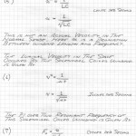
Therefore the Propagation of this Electrification thru the transmission line gives rise to no stored energy and the line can be regarded as a pure resistance, or a simple resistor. The value of this resistor, in Ohms, is given as the square root of the ratio of the Inductance, L, and the Capacitance, C, of the Line. This resistance is the Surge Impedance and is equivalent to the Natural, or Characteristic, Impedance of the Line. It then can be reasoned that when a finite section of Transmission Line is terminated by a resistance equal to the Natural Impedance of the Line, this Line will act as an Infinite Line. It will consume Power Indefinitely since the Terminating Resistor dissipates power away in the form of heat. The Transmission Line is then said to be terminated in its Characteristic Impedance. The terminating, or load, resistor consumes energy at the rate of the Natural Power of the Line. No stored energy exists in the Electric Field of the Line, no forces appear upon the Line conductors. Again the Neutral Condition.When the T.E.M. Transmission Line is delivering power to its natural impedance this flow of Power is uni-directional, that is, it is a one way flow from the source of Potential to the load resistance. All Lines of Force are united into Plancks, no leftovers. If, however, the Load Impedance is not equal to the Natural Impedance of the Line, the flow of Power is not the Natural Power of the Line.
This impedance mismatch at the load end of the line is said to reflect a portion of the traveling wave back upon itself, toward the sending end of the Line. The magnitude of this wave is directly related to the degree of Impedance mismatch. Hence the existence of a Pair of Propagations of Electrification, flowing in opposite directions. The forward and reflected Power Flow, or counter traveling propagation of Electrifications, creates interference patterns on the Line. This gives rise to zones of constructive and destructive interference, these zones appearing as stationary waveforms along the length of the Line. These are known as “Standing Waves”.Standing waves represent the storage of energy, in Magnetic and Dielectric Form, by the Electric Field of the Transmission Line. This again represents a condition of left over Lines of Force. This is to say, not all Magnetic Lines of Force are united with all Dielectric Lines of Force. The left over Lines of Force represent Stored Energy. This stored energy gives rise to physical forces upon the conductors of the Transmission Line. It can be reasoned that these physical forces upon the Line Conductors are the result of Standing Waves on the Transmission Line.
Standing Waves give rise to Stored Energy in the Electric Field of the Line, this resulting in physical forces upon the Line Conductors.The Transmission Line can act both as a Magnetic Inductance, and as a Dielectric Capacitance. One section of Line may exhibit a Magnetic excess and thus behave as an Inductance, and another section of Line may exhibit a Dielectric excess, and thus behave as a Capacitance. The effect of standing waves is to separate the Magnetic Induction and the Dielectric Induction in space along the length of the Transmission Line. Hereby differing physical forces act in a differing manner upon different sections along the length of the Line.
These forces distribute themselves in a complex function of Length along the Transmission Line containing a Standing Wave. The condition of Resonance is maximized when a line is of such a Length as to take one half cycle of time to reach the distant end and reflect back to the sending end. This is called a quarter wave line. If the distant end of this Line is Short-circuited and the sending end Open Circuited, Powerful Resonance is developed. However, unlike a basic LC Tank Circuit, the waveform of the Line will be a Rectangular Wave, abruptly reversing polarity at the time rate given by its frequency of Energy Exchange. This important fact is very often overlooked.In conclusion, the Electric Field of Induction contained in a T.E.M. Transmission Line can be split into a real component, and an imaginary component. The Real Component represents the Consumption of Energy, where as the Imaginary Component represents the surging to and fro of Stored Energy. The unused, or stored energy, gives rise to the formation of Physical Forces upon the Conductors of the Transmission Line. This is analogous to the Real and Reactive Power Flow of Alternating Current Theory. The Real Power is in Watts.
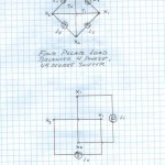
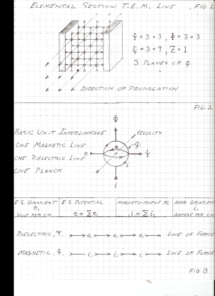
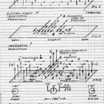
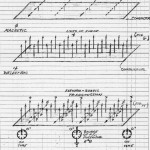
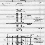
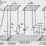
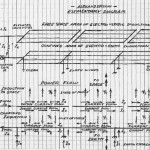
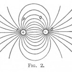
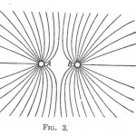
The Reactive, or Image, Power is in Volt-Amperes Reactive, VARs. For the Electric Field the Real Power (Watts) is in Plancks, the Traveling Wave, and the Image Power (VARs) is in Physical Forces, the Standing Wave. Reactive, or Image Power is best called the Activity (VARs), Real Power is best called Power (Watts). The Real Part of the Electric Field is best called Electrification (Plancks) The Image best called Action (—-).Figure 1, an elemental section of a Transverse Electromagnetic Transmission Line. Vertical Lines are Magnetic Lines of Force, and Horizontal Lines are Dielectric Lines of Force. Circles at crossings are Plancks. Note that the Plancks are in planes of Magnetic/Dielectric Lines of Force. Three Planes are shown thus the product of Magnetic and Dielectric Force equaling Q in Plancks is a Planar Process, not a Volumetric Process in this Geometric Representation. Figure 2, this is a symbolic expression of the union of one Magnetic Line with one Dielectric Line. Figure 3 is the gradients in the Lines of Force and their direction of summation into the Electro-static Potential and Magneto-Motive Force. Fig. 4, 5, & 6 represent balanced and unbalanced Power Flow. Figure 7 is the section of the line reduced to a Basic Condenser, or Inductor, and No Propagation is in Effect.73 DE N6KPH
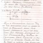
When measuring the velocity difference between underground and our ground, the two seperate receivers can be brought into phase unison by the use of a test oscillator. Both receivers must have a primary tank circuit, here you can place your measurement equipment.The detected AM output, audio frequency, signal is immune to receiver phase shift. This is a property of A.M. detection. Use the audio to measure propagation delay.Wind all coils in the same direction, this is a must! Brass is a very good primary material, good depth of penetration at broadcast frequencies. Wires and clip lead interconnection are the “Road to Absolute Defeat.” Coils and Condensers must be merged into each other in broad surfaces. Stacked metal plates on insulators makes good condensers.
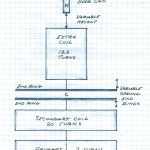
Transmitter air condensers are good, vacuum condensers are the best. A number of small condensers are better than one big one, less stray inductance. Stray inductance is fatal to success! For smaller units silver mica condensers are the only way, use no others. Paralell them on a low inductance bus.Do not get sidetracked, experimental and auxilliary coils as well as patent diagrams will get you stuck in the sand forever. The finished Colorado unit dimensions are all in the notebook. It is all there, look at it, not the diversions, and remember everything you thought was Tesla is the exact opposite. It is there; one or two turn primary; a 20% height/width secondary; and a 100% height/width extra coil, all there, wire size, turns, all there, can you find it? It then can be scaled to any frequency and any KVAR capacity within wavelength conditions.As your unit gets perfected the signal gets stronger and stronger, then diodes start burning out. We then are reaching the engineering objective, that is to light a number 327 pilot lamp. Not much power but too bright for Einstein.
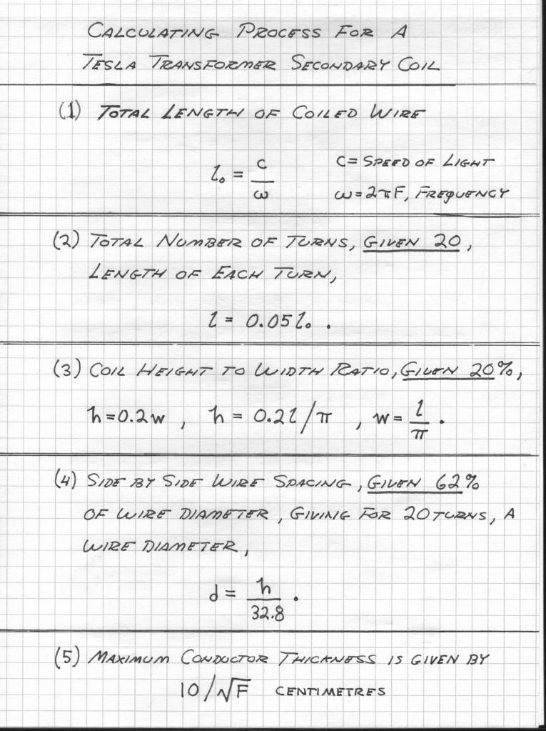
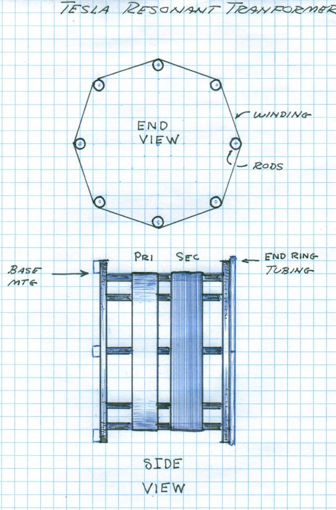
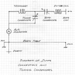
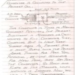
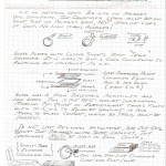
The sheet conductor is closely spiralled into two turns, for a secondary of twenty turns. For a conductor thickness as given by the maximum thickness vs frequency the volume of the primary metal must equal the volume of the secondary metal, based upon equal weights for primary and secondary metals. Brass can be 1.7 times thicker than copper, and bronze can be 2.8 times thicker than copper, for a given maximum thickness and frequency.The primary condenser should be made of the same amount of metal as the primary coil. Their weights should be about the same. The connecting leads must be short and the same width as the primary conductor. Large, multiplate air condensers are good, so are metal sheets and glass.The secondary capacitance is best a copper tubing ring around the outside of the H end of the coil. This ring must be open in one spot along its loop so as not to be a shorted turn. The end of the secondary wire connects to this capacity ring. Beer cans make the best elevated capacitors.The finished transformer must operate on a directly connected ground plane. A large plywood table with aluminum foil glued on to it, this covered with a plastic or glass sheet is the minimum required ground plane. Obviously the aluminum plane must be solidly earthed with special attention to minimizing ground lead inductance. In order to light a lamp a more broadcast station style of ground plane is required, but for testing purposes the metallized plywood “ten by” sheet is just fine. Good luck and good crystal set DX ing.
And it came to pass, thru the years of 1978 to 1982, that the occurrence of a certain sequence of events took place at a small coastal town called Bolinas, California:Within my laboratory at R.C.A. Bolinas, I had just completed my first full size Dipolar Tesla Transformer. It was a 500 kilovar unit. This was the product of efforts beginning in my childhood. The objective, physical realization of “Cosmic Superimposition”; the verification of the “Theory of Creation”. This seemingly harmless endeavor was to create for me a life of eternal persecution, even before I started!Two very important visitors arrived at my BL laboratory, Philo Taylor Farnsworth III, and his mother, the wife of the “Inventor of Television”. They had come to see the “Galaxy in a Lightbulb”. This visit was encouraging, however soon after I was shut out of my BL Laboratory by R.C.A. The Tesla Transformer immediately vanished, and Commonweal destroyed most everything else over a period of time.
Earlier in life, my San Francisco Laboratory at 1360 Howard Street was obliterated, and my stored gear at Pier 3 in Fort Mason was junked. About 10 tons of R.C.A. gear was lost forever. To finish it off Commonweal smashed the rest left behind at R.C.A. Bolinas, about 30 tons total. Soon after my Radio Propagation Laboratory at Sonoma State College, with its priceless R.C.A. dual diversity receivers (SSB-R3) vanished to the winds, this along with surviving R.C.A. records and notes, including the complete blueprints for the 1919 Alexanderson Network. Some of the notes were by Alexanderson himself. All gone. Then R.C.A. went to the bottom like the Titanic. Not much different than my life now IS IT?! But I was only 30 years old that time around, in the cycle of the Continuous Destruction of my efforts. Afterwards, I lived in a box in the bushes in the Town of Bolinas, foraging by day and crawling back into my hole at night, a Human Rat. I actually learned to enjoy rat life, and it had many advantages not found in so-called “Real” Life. But the women in the “Real” Estate office did not like it at all. The box in the bush was close to a house owned by some crazy guy who claimed his father invented Television. Right, and I am Nikola Tesla. One day he invited the rat inside.When I first met Farnsworth, we were not likely friends. I was an “R.C.A. creation”, and R.C.A., aka David Sarnoff, was the Arch-Enemy of the Farnsworths, this for good reason. I may have been a Human Rat, but Philo did not look so cute either. Years of his own Commonweal Harassment, along with drugs and alcohol, had left Philo a complete wreck. However, I had lived with this on the street before, so it was fine. As the gallon bottle of wine found its way into our bellies our discussion turned to favorite “Sea Tales” of self edification, and the boasting began.
After attentively listening to Philo’s account of how he got into M.I.T. at age 16, this without his parent’s knowledge, I knew I was “one upped”. My tale was only of R.C.A. at age 16, and my parents and school helped. But maybe I did have an even better tale. Next I expounded an event of childhood in the laboratory of my parents garage. My half of the two car garage was crammed with a Few Tons of combined R.C.A. gear from Bolinas and Navy gear from Standard Surplus in S.F. The assemblage was connected directly to the main terminals of the house circuit box. During the intervals in which the parents went out for guaranteed periods of absence, my high school buddies would arrive. It was time to play “Nuclear Meltdown”. Nuclear Meltdown was great fun and looked like an episode right out of the 1960’s T.V. show “Outer Limits”. That was our primary aim. It was however also the dread of the neighbors. Now only did playing Nuclear Meltdown dim the lights in every house on the block, but it also wiped out Television reception for miles. I later learned in the Navy that Nuclear Meltdown even appeared on the Radar Indicators at nearby Hamilton Air Force Base.
Philo convulsed a bit at this point in the story, but not because it was a better one. The radar effects meant that playing “Nuclear Meltdown” created a Controlled Fusion Reaction! In Philo’s mind my connection with R.C.A. was not an issue anymore. I had replicated his father’s fusion work and the Farnsworths had kept this work a secret from public knowledge. Well, you don’t know any better when you are a kid, do you? (Don’t try it today).
It was however that my own interests were more Electrical than Electronic, and Farnsworth was indeed the “Master of the Electron”. My own work, this within the giant Cathedrals of R.C.A., with their Megawatt Polyphase and High Frequency Power Systems, led me to Tesla and Steinmetz, the masters of electricity. Also, the Cosmic Inductorium, as it is properly called, is a Goethean concept, where the Farnsworth Fusor is a Newtonian concept. Farnsworth’s work was outside of my field of endeavor.
My own efforts at this time were directed towards the Steinmetz Versor System, this leading to a better understanding of my Experimental studies and Discoveries. But Philo took an unexpected interest in my Steinmetz work. He and his mother had just finished with their efforts to start a postage stamp series commemorating “The Four”, Farnsworth, Steinmetz, Armstrong, and Tesla. But this was only a historical interest, who cares about the Electricity in the Square Root of minus one anyway? But Philo did, and he made a noteworthy remark: Philo stated that “if you were to develop a system for the Hyperbolic Functions, rather than the Circular Functions, then you would have found the Holy Grail of Electrical Engineering”.
He offered no explanations on this remark but then gave me one of his father’s books. It was “Physics and Mathematics in Electrical Communications” by Perrine. This was the genesis of my work in Versor Alegebra. Now 32 years later, here we stand, in the same hole. Break, more to follow.
DE N6KPH
References,
(1) “Physics & Mathematics in Electrical Communications”, Perrine.
(2) “Farnsworth Writings” of Vassillatos.
(3) “Distant Vision”, Elma “Pem” Farnsworth.
(4) “Empire of The Air” P.B.S. Video.
(5) , (6) are Censored, (E.P. Dollard)
(7) “Bolinas Barbera Boxer” E.P. Dollard.
(8) “Borderlands”, Outer Limits T.V. Program.
(9) “Die Kunst Der Fuge” BWV 1080, First Fuge, J.S. Bach.
3) Thomas Clockwork; a time piece for the use as a frequency standard of a known omega.
4) “Symbolic Representation of the A.C. Wave”, E.P.D.; a shipyard engineering paper, not a book really. E and I, as well as the rest, P, etc., are readings on the scales of electrodynamic , or moving vanes, switchboard instruments.Navy power switchboards contain numerous instruments (relays, meters, etc) for the analysis of complex power flow. The instrument knows not of the actual derivation of e, E, i, I, only the net effect.
5) PI over two; this factor appears twice in the Crystal Radio Initiative, C.R.I. The (20%) secondary coil “effective” propogation velocity is the velocity of light in the space in which it occupies. Here the Pi over two factoris an offsetof a unit value to shorten the winding to compensate for the heavy external loading that the secondary is loaded with, that is, the external inductance and capacitance from the earth and extra coil connections. The aspect ratio of 1 to 1 on the extra coil gives an “effective” propogation of 187% the velocity of light, hence the winding length must be made greater in order to get a quarter wave resonance at a higher speed. This is brought down to Pi over 2 percent, 157%, the velocity of light to compensate for the burden upon the extra coil, this mostly arising from the dielectric upon which this coil is wound. The secondary is Pi over two shorter, the extra coil is Pi over two longer. Golly Mr. Wizard that’s Pi squared over four! Do not hunt for magic where it is not, this is all experimental. So go experiment.
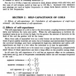
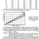
6) 62% spacing; an empirical factor, no hidden cosmic secrets here. For its origin go to “Radiotron Designers Handbook”, by R.C.A. in Ausstralia. The article “Short Wave Coils” is the basis for the 62%, and the article “Self Capacity of Coils” gives the table for self capacity and the hyperbolic variation with coil dimensions. Referenced are coil pioneers, Butterworth, Medhurst, Autstin, and many others.
7) Conductors; metal does not conduct electricity, this is a primary mind virus. When it is e, or i, the metal bounds the electricity, when it is E, or I, the metal translates the electricity. This is an extremely vast subject so wait. Resistance is NOT one over the conductance. No it is not! The ability of metal to “conduct” is in direct, not inverse, proportion to the square root of the resistance of the metal. Also the more the metal “conducts” in this manner the more the surrounding E.M. wave is slowed. Thus large deviations from the luminal velocity are found in transmission systems in which the physical mass of the conductors all take part in the flow of electrification.
8) Underground vs over ground. Two identical Tesla units will not compare. They cannot receive E.M. waves. For over ground use a conventional crystal set with a dipole, not a ground Marconi antenna. A loop type receiver is even better, a big loop over ground and a big star radial underground. Thus a dipolar connection over ground, a monopolar connection underground. The Landers Mojave Research Installation used a beverage over ground and a wideband Alexanderson underground.
9) The energy required to drive a crystal diode is the same as a telephone signal. So amplifiers are not a way to make it more sensitive. A conventional A.M. radio coupled to the Tesla Transformer is the proper way to add gain (electronic gain) to the system.
73 DE N6KPH
And it came to pass, in the year of our lord, Feb. 14th, 1989, an activity took place in the small coastal town of Bolinas, Ca:1) Tom Brown, Eric Dollard, and John Costa, proceeded with an attempt to produce a video documentation of the Marconi and Alexanderson remains in the R.C.A. Bolinas antenna field. There was no real plan, it was more of a free form venture. In a conjunction with our endeavor was a planetary alignment and near record solar activity. The perfect day! You could feel the tension in the air.2) Commonweal had got wind of our video event so their minions in town began the usual harassments. Needless to say the day was filled with voo-doo, and a small cloud followed us all throughout the day as an indicator. I had been blacklisted by R.C.A. at this time in history so there were no friends around for our effort. It is however that R.C.A. Bolinas is a “Cosmic Inertie” for Planet Earth. Even before Marconi the Indians were in awe of the “Hole in he Sky”. To compound the voltage, long intervals of “Die Kunst Der Fuge” resonating through the “Cathedral Like” Marconi building, as well as a few masonic versor operations, were conducted during my prior use of the Marconi building. The perfect day at the perfect spot! The cosmic anode.
3) The recording began and relentless battery problems plagued the effort. Then the batteries all were dead. Now what? Tom gets the lame idea that R.C.A. will help us, right! R.C.A., and also Commonweal, have been trying to rid themselves of the “two legged coyote” for years. Tom insists. “No one at R.C.A. remembers you, so let’s go”. After ringing the door bell the “coyote” cringes and begins to sneak back into the bush. But a new guy, Wayne, answers and welcomes us inside. He became somewhat puzzled when I already knew that all the receptacles in the station were wire grounded twistlocks, so we would need the adapter. About this tiem the “Geiser” shows up in the control room, he worked to close my lab there along with station manager Ed Brennen. Upon his cognizance of my presence, a certain siezure overtook him, like the lady that turns to stone in the Bible. The frozen expression on his face was indescribable. So we bailed out, but with charged batteries. (Wayne was awestruck)
4) We continue down to the beach and then back around for the final scene, the “Fallen Cruciforms” of the antenna wreckage. The batteries were used up. We see a government vehicle working its way towards us from the road. Well who shows up for the event but the head of the Park Service himself, Mr. Sansing. Mr. Sansing came with a special message for me!
“Mr Dollard; we have a group to make sure that there is to be no more electrical experiments here ever again, do you understand Mr. Dollard”.
5) No I don’t understand, but I know who is in charge of their group, Burr Henemenn. Later in the week the “Gieser” put on a set of headphones. He bypassed the safety interlocks, and walked into BL-10. Upon connecting himself to the 12,000 volt anode terminal he was blasted.
73 DE N6KPH
2) Later, through the writings of Vassilatos and his pictorial “Vril Compendium” my childhood archetypal memories of R.C.A. Bolinas came back to me. Now I had the complete picture in my mind of the pre R.C.A. Bolinas configurations from 1913 to 1919. (1998)
3) Next in my effort was to write a book combining the book/video “Empire of the Air” with the visual portrayal in the “Vril Compendium”. At the same time the park service initiated their own book on the history of this important facility, which at the time was operationally intact as station KPH. The title of the first is “Electric Wave Telegraphy” by E.P. Dollard. The second is “Wireless Giant of the Pacific” by local historian Dewey Livingston. Both of these books are censored.
4) Censored, but censored by who? The parent agency of this censorship is called the Golden Gate National Recreation Area, G.G.N.R.A. of the U.S. Park Service, Dept. of the Interior. The local office directly enforcing this censorship is the Point Reyes National Sea Shore, Olema California. The principle operatives are;
1. Richard Dillman – Green Peace executive
2. Thomas Horsfall – L. Livermore technician
(whales and bombs)
These two run a fraudulent historical society, MHRS, this society is now forcing all Navy and radio historical sites into its control, a syndicate.
5) Borderland sciences held vast quantities of my R.C.A. research and it all just vanished to the winds. Also every R.C.A. paper at Landers also vanished, and now the station itself is gone. This is in part due to an effort by the “Integratron Goddess Temple”. And now we have the so called “Tesla” society, what a joke. It is another Einstein society, no Tesla. This outfit is run by a Georges Gaboury, of San Francisco, Ca. It is of interest to note how he consumed millions in capital fighting for another free energy moron that gets himself in trouble, but in two years did nothing about the priceless Landers installation and even refused to mention it in his newsletters. His handler is Charles Ostman, and you guessed it, he is from L. Livermore Labs. (Also the Hell’s Angel’s swine that got my dog is tight with L.L. Labs !) Ostman uses the “Tesla” group as a platform for his expression of neo-pagan quantum mysticism, and its rising Goddess Shiva. His videos are readily available from the “Tesla” society, but not mine.
6) As a side note, a Congress Inquiry was conducted into the situation in Bolinas and this had been held by Barbara Boxer. My following letters or “online” as the “Barbara Boxer Report”. Make a copy before it disapears. It would be great fun if every person reading this physically send a registered copy to her office, requesting the F.B.I. documents on the Bolinas matter.
7) So are we dealing with a government conspiracy, an international communist conspiracy, or just a concatenated string of human filth? The U.S. Coast Guard also operates a giant radio facility in Bolinas, station NMC. The Coast Guard took great interest in my Bolinas efforts and they even offered refuge for me from hostile Park Police. It hereby can be inferred that they were not part of the conspiracy. Their efforts to get involved in my conversion of R.C.A.’s KPH station were hampered every way. As a final “slap in the face” the entire KPH facility was handed over to Green Peace MHRS, and Green Peace is an AVOWED ENEMY OF THE US NAVY!
8) Years later I dropped by Coast Guard station NMC to see how things were going. The commanding officer I knew, as well as the master chief, were at new duty stations now, so I expected the usual difficult introduction required in order to enter a military installation. That was not required the first class (Mate) came out and seeing my military Corolla says “Oh you’re that guy”. Looking at his fellow sailors nervously he ask me to join him in an antenna inspection. When we got beyond hearing range of the crew he asks; “Who are these people anyway that come here and tell US that we are not to talk to you???”
73 DE N6KPH
Some time ago someone put out a picture of a coyote, and the coyote asked about the idea of A Hollow Earth. This is a persistent story, however, I cannot produce and engineerable concept of a Hollow Earth. The existing algebra for gravity is not well developed. It would seem possible however thru Functional Thinking that such a physical condition can make sense. This could lead to a functional Theory, so let us give it a try.
(I) To begin, science today exists in a Direct Analog to the situation with the Catholic Church in the years prior to Martin Luther (1499). Reading, or even possessing a Bible, was a Capital Offense and the penalty was Death. The “Church” was taking steps to ban music in their structures and this sparked the Lutheran Revolt. You were required to pay your own way into Heaven, to the Church of course. You will not need money in Heaven anyway. Great monarchs feared the wealth and power of the Church, ask the Knights Templar. By the way what ever became of Jesus? (He Died)
Verily, this is “Science Today”, a sort of T.V. show. The Pope is now Al Gore, and it is that the Pope has many Bishops, and in turn the Bishops have many Priests. We have met some of Them in the Town of Bolinas, Hillary’s “Village”. But the Bolinas station pre-dates these people. And as Tesla said, “they are no more than microbes of a nasty disease”.
The R.C.A. Research at the Landers Installation continued the scientific study of the Interaction of the Earth with solar and cosmic forces. Here is the starting point for the knowledge of the Earth’s Interior. The physical mass of the Earth is here found to be alive with mechanical and electrical impulses and oscillations. These are continuously active often reaching astonishing magnitudes. Leveled cities and incinerated substations serve testimony to these wave-forms, and these seem to come from nowhere.
The Landers Installation contained the highest sensitivity and fidelity seismic recording system in known existence. In proportion to the standard (U.S.G.S.) systems, the one at Landers was 120 decibels more sensitive. A mosquito is now a jet aircraft. Also advancements on the Alexanderson system produced a network serving as a “Radio Telescope” for reception of Telluric Currents in the Earth. This also was of high sensitivity and fidelity. Here the amplifier theories of Bell Telephone Labs, along with Navy requirements of reliability and electro-magnetic compatibility, this with Western Electric Construction Practices, led to a remarkable “Bell System Installation”. But it is gone! (See the American Marconi website for pictures of this installation before they vanish like the rest.)
Here then existed a complimentary pair of systems. One was the Seismic Recorder-Indicator receiving mechanical vibrations from within the Earth, the other was the Telluric Recorder-Indicator receiving electrical vibrations from within the Earth. The sensitivity was normally set in the range of one milli-micro watt on both systems. This is one million times smaller than a telephone signal.
Among the various findings at this installation we will focus upon a few basic relations.
1) The mechanical waveforms and the electrical waveforms during significant events are directly inter-related with each other.
2) These electrical waveforms lead, in time, the co-responding mechanical waveforms. This time angle is from one half to two rotations of the Earth. The Giant Japan Quake was two rotations.
3) Lightning Impulses arrive at the Alexanderson underground antenna ahead in time of the lightning impulses at the beverage over ground antenna.
4) The telluric signals are in no way related to any so called “Earth-Ionosphere Waveguide”. These signals definitely originate from the interior of the Earth.
5) Both mechanical and electrical waveforms often become sinusoidal, particularly before a Major Event. This is to say, both become alternating waves. This is important.Theory:
Because there exist “sine waves”, that is, circular functions, these waves thus represent natural harmonic frequencies of the Earth itself. This observation indicates that the Earth is hollow. The Earth, mechanically is hereby a huge “Helmholtz Resonator”, and electrically it is hereby a huge “Cavity Resonator”. Also, as explained by N. Tesla, the “Earth-Ionosphere Condenser” is far too thin to support any wave-guide modes. Only electro-magnetic waves parallel, of magneto-dielectric waves normal, to the surface of the Earth are possible. This sends the notions of T. Grotz, or The Corum Gang, to the dumpster. Again it is food for the crows and the rats, they love it.
(II) There exists no real engineering “Theory of Gravity”, none. There is no “Tesla Theory”, no “Einstein Theory”, no Theory at all. All we have is guesswork and speculation, nothing for the engineer. All we have is the basic algebraic expressions of Newton, and the observations of astronomers. Gravity tells us what to do, we do not tell it what to do. Hence the idea of gravity is akin to the idea of God, unknowable. But to be sure we do have no shortage of priests muttering in Latin.
Since age six I have been turning wrenches, filling test tubes, and discharging condensers, etc. It might be possible that at age sixty I may have acquired some archetypal sense of physical reality. With no more than this “heuristic” sense and in the “Coyote Like” manner of Thomas Alva Edison, let us attempt at a basic “Theory of Gravity”.
The notion that the force of gravity increases in intensity toward the center of the Earth, reaching infinity at the central point of singularity, makes no sense to my engineering mind. I cannot see how to build it, something just does not seem right. It is an axiom that isolated masses in free space congregate toward one another, and draw together upon vectors on their “Centers of Gravity.” It is also, however, an axiom that the outer masses shield, or screen, the inner masses of the congregation. The physical model is throwing a batch of marbles out of the space ship into free space and watching them congregate. What will they do, can we see it on “Youtube”?
The Earth itself is a contiguous mass, and it is postulated by contemporary dogma that all force vectors are radially directed towards and into the center point of the Earth. This is certainly true at the surface but what about inside. But wait Mr. Wizard no mass is left in an infinitesimal singularity to draw anything, all the mass is now outside of it!
It may be best to consider gravity to be based upon causes external to the physical body exhibiting the effects of gravity. This has already been done for electricity, despite the fierce opposition of the “Catholics”. The force of gravity inside a body is then in analog to the depth of penetration into a metallic body by electricity. This is known as the skin effect. In this the force of gravity would be a space integral not unlike that for magnetic penetration into a metallic body. Now the force of gravity can even reverse direction in analogy to electricity within metallic bodies. Here then the “Center of Gravity” would exist at a finite depth below the surface, and also a finite distance from the center. This condition could give rise to an inner surface and hence a Hollow Earth. Let us take a tentative value of about a third in, near the value of one over epsilon, the log base. This establishes the inner surface upon which to stand. Now your head points to the center of the Earth, whereas, on the surface your head points to the sky.
(III) To stretch the Theory of a Hollow Earth to heretical extremes. Let us suppose that at the center of the Earth at the singular point, this in a photo emissive spherical geometry, there exists a “Farnsworth Star”. This star provides the radiant energy for life within the Earth. Its radiant matter provides a continuous supply of “electrons” to the body of the Earth, this is explaining the so called “Negative Charge” on planet Earth. Taking this to fiction is the movie “Journey to The Center of The Earth”, the original, not he adulterous (censored) re-make. Watch this movie.
Finally, we can take our notions of a Hollow Earth to the “Art Bell” level, la-la land phantasy. There are those who claim that there are people who live in the Hollow Earth, and they travel to our surface world thru a passage within Mt. Shasta. I myself try to avoid these things, if I can.
This takes us to the Landers Installation of George Van Tassle. Contained in his Landers Installation was a hemispherical structure approximately 50 feet in diameter and thirty feet high. This structure served as a magneto-dielectric transformer, operating at a potential of 100 kilovolts. This is the same potential as used by Marconi and Alexanderson. In a strange way it seemed like the Wardenclyffe Dome had come back and was waiting. George Van Tassle called it the INTEGRATRON. This structure was founded upon archetypal Four Quadrant relations. The central figure is known as the “Solar Cross”. Van Tassle wrote a book on the Four Quadrant Theory called “When Stars Look Down”. Then (1978) Van Tassle was no more and his installation went to hell and beyond. (Not much different today).
Later on in time, about 1982, the Integratron Installation gained a new superintendent, Donald Floyd Lockwood. (We always referred to him by his last name as in the Navy). Lockwood has now a problem to solve, this is where to find an engineer who can figureout how to make this extra-terrestrial apparatus work, with no blueprints or design formulae. Well, I wish you luck!
One day Lockwood entered the galley of the Navy LSM I was working at the Richmond Yard. He had got wind of a “Certain Naval Electrical Engineer” that may be the one to “finish the dome”. Lockwood tells me that he has just come from Mt. Shasta where he had met with a lady who “walked out of the mountain”. She had given him a symbol, or diagram, and this would prove the identity of the engineer. Before I could get pissed off he puts the diagram next to my open notebook on the “Symbolic Representation of A.C. Waves”, page six. The diagram on page six and his were IDENTICAL!
73 DE N6KPH
1) People do stupid things. One is having your dog chase a pack of coyotes. Once the dog is out of your sight the coyotes will kill it. An even more stupid thing is to fire a shot across the bow of a U.S. Naval Vessel, this is suicide for sure.
2) And it came to pass that Joe Blow refused to believe the cross phased generator was electrically rotating backwards. He violently exclaims, slobbering on the switchboard in the process, “There is no backward rotation, look, the sync lights go dark, see, both generators are 60 cycles see, so where is your F***ING Backward Time!” Joe Blow closes the generator breaker and a massive blast results. The entire ship loses power and now is adrift. The ship finally capsizes, killing 20, including Joe Blow.
3) T-Rex (Tyrannosaurus Rex, or terrible lizard). A large agressive reptile that bites and tears flesh in the course of its daily existence.
4) So, Joe Blow from Kokomo:
Cease and desist from your disruptive argumentations. You argue using terms you do not comprehend. Further you force your mal-aligned understanding upon others, relentlessly. This pathological behavior is best suited for the pissing wall behind the “Hoon Saloon.” If you have no interest in antennae, no interest in anyone’s hard earned theories, such as lamare, and if you are defiant against Steiner-Steinmetz projective geometry, THEN GO FIND ANOTHER FREQUENCY jackass. The toilet is made for vomit, not the kitchen sink, so how about a nice big QRT!!
NFG DE N6KPH
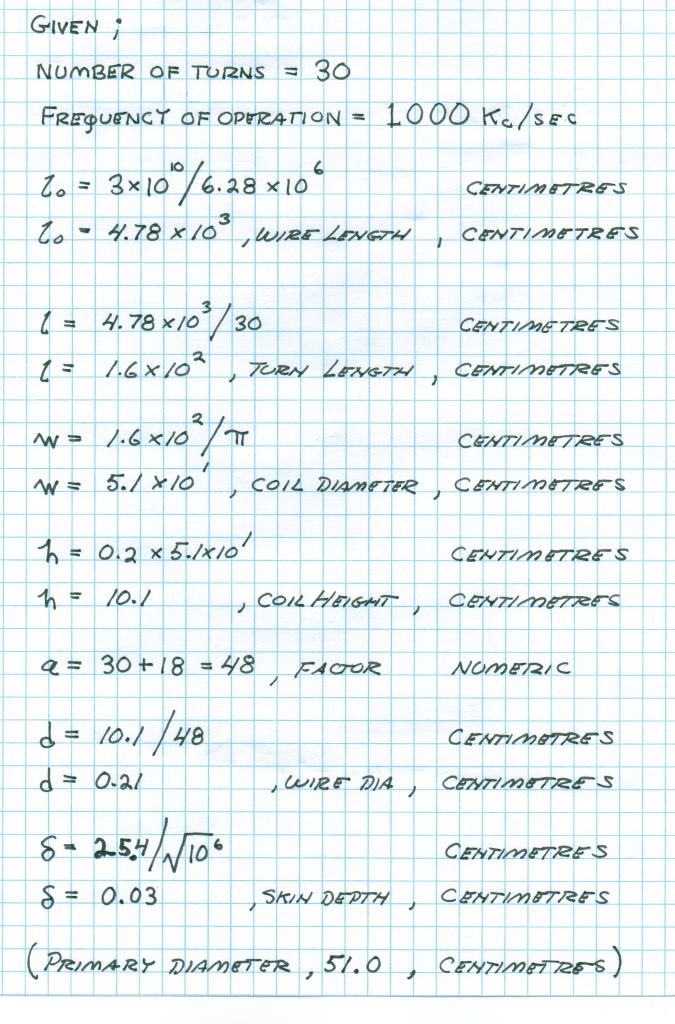
While the “Captain’s Mast” was the fate of Joe Blow, the Mr. Wizard achievement award goes to Geo-Algebra. This is for the meritorious effort in determining the frequency of the C.R.I. coils. 1600 Kc is just what I wanted. This can be loaded by a variable condenser down into the center of the broadcast band. More on this later.
While the greatly increased activity on this forum is very encouraging, La-Mare is drifting far off course, and this is compounding the confusion. The “T.M.T.” and the Tesla Coil are not distinct modes. Also Meyl is a waste of time and I see a new trend coming to distort Tesla’s real objectives. The “Tesla Coil”is not an antenna. Two modes do exist however, Telluric Excitation and the Earth-Ionosphere Condenser (Air). Excitation of the Earth-Ionosphere condenser runs the aeroplanes. La-Mare’s biggest error is the insistance upon a transverse component, that physics poison from his university training. The L.M.D. is NOT, NOT, NOT, the T.E. or T.M. The L.M.D. wave has both Phi & Psi in the direction of propogation, there is NO transverse component. Also it would be helpful if La-Mare would stop using the term electric for dielectric. This can only hamper the Steinmetz view on electricity. I went thru great efforts to set the wording right and it would be nice if we could stick with it, or is it that the curse “College Education” causes permanent brain damage? Also La-Mare may find my M.W.O. Antenna (Which Lindemann profits from), may be his moon bounce antenna. I will credit this however, La-Mare’s theory about the circumference and length Pi over two factor is getting me thinking, something lurks here of importance.
A lot of work on my part is required to discuss these things but the forum moves faster than I can write in the driver seat of my Corolla.
This is an outline.
1) Are we sure mutual inductance M is rotational. We know nothing about M, NOTHING.
2) The La-Mare/Thompson Longitudinal Dielectric force cannot be a wave if only one energy exists.
3) Here is the very critical question, does a displacement current in a dielectric really produce a magnetic field? I do not believe it does.
4) The dimension of time appears with Dielectricity in three forms:
(I) Coulombs per second, or Ampere
(II) Farad times Ohm, or Second
(III) Siemens per Farad, or per Second
Break more to follow
DE N6KPH
@All Crystal Radio Builders via Web000x:
Eric would like to get some feedback on his given TMT design formulas. The following is a test procedure used to determine the resonance of the coils.
The best way to get him the data will be to mail the results to the Lone Pine general delivery address.
Dave
I have recently returned from a 600 mile trip into and out of “Babylon”, this in order to read new interesting material on this forum. I had noticed bits and pieces of this here in the “free world”. Well lo-and-behold when I landed in Babylon and looked on the forum all this material had just vanished like a “fart in the wind”. Then further, to “throw poison into the soup” is the yammerings of Joe Blow from Kokomo.
Let us develop an animal story. Joe Blow exists in analogy to a Trichinosis Cyst. In this is a small parasitic organism, a worm so to speak, that lies dormant in the human body, it awaits the proper conditions for growth. This parasite kills by consuming the muscle tissue of its host. It is contracted from the ingestion of pork.
Joe Blow was awakened from its dormant condition by the exposure to “Negative Time”. This is a concept that made it violently squirm. Considering this fact, it is quite possible the organism can be eradicated from the victim host by heavy exposure to B.W.V.-1080. So, let us travel backward in time. On the date in time of April 3 it was presented on this forum a page from C.P. Steinmetz where he plainly states that in A.C. work R is not equal to one over G. This is very basic Electrical Theory. Now it came to pass, in response, Joe Blow displays on this forum, on or about the date in time of April 4, the same aforementioned Steinmetz page. At the bottom of the page Joe Blow exclaims that Yes indeed R is one over G, the opposite of Steinmetz’s own words! What are we to think, is this a pathological situation?
This is an open and shut case in my mind. Joe Blow is hereby charged with willful and malicious interference to a civil communication channel. Where now is the F.C.C? Ham radio operators call this intentional QRM. In the military it is called “Enemy Jamming”, and hereby I must engage the C.R.M.-114 between myself and this forum. General Turgison, U.S.A.F. Will brief you on the function of the C.R.M.-114. (“Dr. Strangelove”). The O-P-E is my postal addresss, this will circumvent the QRM. Hereby specific questions can be responded to, without harassment.
Next, for Lamare: His story is developing into the arch-typical example of what a college “education” can do to the human mind. Here again we meet with a pathological condition. As a case in point it is to be noted that it was put forth on this forum a very basic engineering proposition, the forces acting upon a D.C. Powerline, like the one I am looking at as I sit here now. Assuredly one possessing a “Masters” degree in electrical engineering could provide an answer very quickly, at least one would think so. But the response to this and other important questions was only quantum babble. I would suspect that these “high degree” engineers could not even wire a D.C. switchboard on a tugboat, not even at the point of a gun!
There can be no excuse here that I have not provided adequate material to further the longitudinal transmission initiative, the Steinmetz Sphere in space, the Steinmetz lightning wave and the resulting Marx Generator, the waveguide modes, and even the J.J. Thompson idea that a displacement current in an insulator does not give rise to a magnetic field. However Lamare just side steps it all and gives us another later of Quantum-Bearden Coyote Puke. For all the volumes of material that I have put on this forum little of value has come back from these pendantic “high degree” engineers and physicists. Hence my “experiment” here on this forum has shown the college “education” to be useless for the understanding of electricity.
Verily this forum is not a kitchen sink of ideas but it is more like a Greyhound bus station toilet bowl filled one foot above the seat. I have no inclination to engage in a “Bengal Squat” on the seat of this forum. However I will continue to transmit on the forum as usual, this as before is directed to the “Silent Majority” such as conceived by R.M. Nixon. All material is given from the standpoint of electrical engineering and ham radio. The directive here is the physical and mathematical experiment, only thru experiment can useful engineering knowledge be gained.
It should be remembered that I am not here on this forum because I really want to be. My presence here is only a consequence of a concatenated series of disasters, a lost coyote, an impaired Corolla….abject destitution, all this in a nation of absolute swine hurtling into a violent self destruction. That is how I ended up here. My real ambition is to put my efforts behind the fence of a military installation, not out to Bevis and Butthead in the Greyhound station. After all this is what the Landers Installation was all about, a confidential project for government use only. This is what I once had and this is again what I want. (Is the Navy listening?).
On a much darker note we are being plunged into another Dark Age, the Sun is even going dead. This will be an era of Scientific Totalitarianism. This is the Al Gore, Commonweal, Grean-Peace, all fruiting bodies from the mycelium of The Beast. This is “the group”. It is quite ironic however that they are not really the friends of the Navy. The harassments by Barbera Boxer is one example. Now the Navy is expected to be a prostitute for the “Clinton Global Initiative”. And “the group” does not want you think back to the fate of the AGTF-5. No backward in time! (History)
Eddy Hartzenstein, also known as “The Los Angeles Times” is an ardent advocate of Scientific Totalitarianism. Hartzenstein exclaims in his editorials that the Theories of Relativism, Evolution, Global Warming, etc. must be made LAW! Hartzenstein goes on to state that “one should not have an open mind” on these theories, there must be no more discussion. It does not end here, Al-Goreda aka The Commonweal is developing legislation that says questioning the “State Science” (S.S.) is to be considered a “hate crime”, this to be enforced by none other than the A.C.L.U. (Anti-Christ Lawyers Union). Can we see where this is going, so all I can say is
QRT DE N6KPH
Tesla Coil Build help for “Juliet Charlie” aka Geometric Algebra – Sent by snail mail April 24th 2012
2nd Tesla Coil build help Document
I have just been given the opportunity to view the E.F. forum by a passerby in the “Anarchist Cafe” here in Lone Pine. I am very pleased with the experimental efforts that have taken place with the Tesla Transformer. Also the bus station toilets have been cleaned out and are ready for a new load.
Geometric Algebra has basically duplicated the Tesla Colorado Pri:Sec setup in a scaled down form. His effort is quite scientific and thus helpful. Dr Green actually constructed exactly what I had specified, how extraordinary!
The effort however has fragmented into three incongrous channels,
(1) Eric Dollard
(2) C.R. Magic
(3) T.M.T. Replication
This is not the best thing to happen, one hand knows not the other hand. Most of the productive experimental effort is found on channel (2). Two important engineering prospects result:
(I) A global network of synchronous Tesla Telluric Transmitters and Receivers
(II) An A.M. broadcast repeater using the Tesla Transformer to bring DX A.M. stations to isolated distant communities, a passive system of rebroadcast.
Do not forget to involve the F.C.C., they do not like being left out of things “radio” and actually they are looking for a bit of fun also! Experimental work is allowed on 400 Kc/sec the Industrial, Scientific, and medical allocation.
On channel (3) of Farmhand, Dr Green has a finished unit. Now some response curves and magnification ratios of this would be nice on the forum. This is science in action. However on this channel my warnings about transmitting on the A.M. band are ignored. The F.C.C. also thinks its fun is to ream out A-holes, so let us see how long it takes for them to show up. Spark Gap transmission on the A.M. broadcast band is a great way to invite the F.C.C. to your home!
I myself have no interest in fighting in Farmhand’s sandbox, but it will be instructive to see how long it takes to get in hot water with the government. It is so easy in today’s world. (911)
Remember, maximum power is 100 milliwatts, it’s the law! For more power a push-pull dual counter-wound transformer pair on 400 Kc/sec is legal. Drive around your home town with an A.M. radio and see how far you A.M. signal travels, you may be shocked at the distance. Report your findings on the forum for others to see, science in action.
Break more to follow,
73 DE N6KPH
Notes on Tesla Transceiving 2:
You are all playing with my first fully mathematical design, no books, no experiment, just a pad of paper in the seat of my Corolla sitting in between giant rocks, one 14,500 feet high! And you all have shown it to work. It must be noted here the given extra coil is a compromise, Colorado Unit will not completely scale down to broadcast band without excessive turns of fine wire on a tiny extra coil.
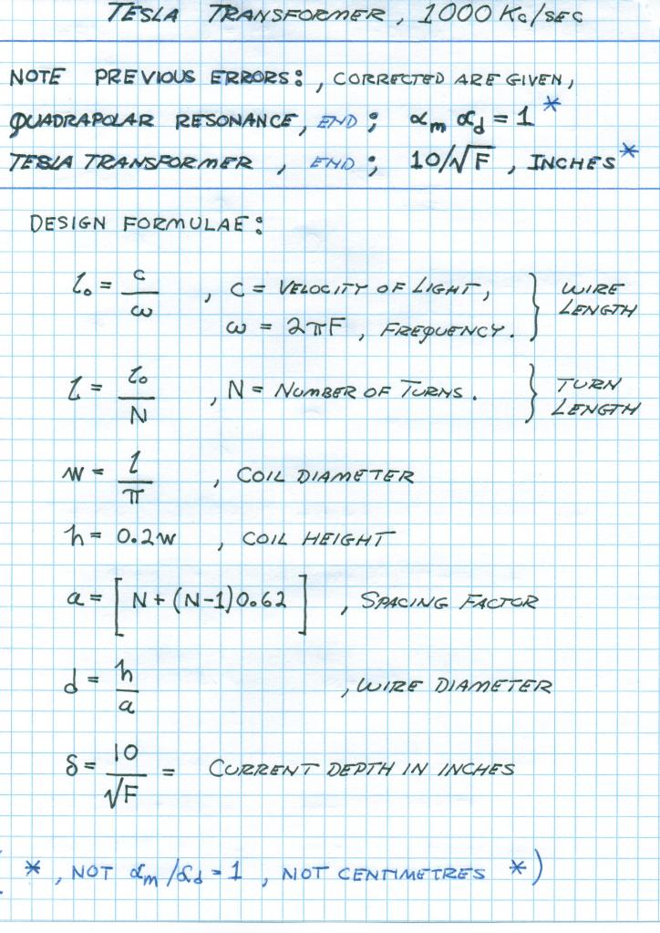
Note that a primary condenser is a must and it must match the KVar of the primary coil. Equal surfaces or equal weight for coil and condenser, a good “Rule of Thumb”. There must be no breaks, gaps, etc between the coil and condenser, NONE! Tesla says this in his refined designs. (Fig 1)
The final setup at Colorado Springs, the FINAL ONE, should go on forum;
1) Coil heights, widths,
2) Number of turns,
3) Wire Gauge, and number of wires in primary bundle,
4) Length of wire in secondary and extra coils,
5) Operating frequencies,
6) Primary condenser connections and auxilliary devices in with the primary system
This is of extreme importance, do not get hung up on test coils, un-related experiments, or early transformer construction, we want ONLY his finished product known to be his final perfection for earth resonance. Can anyone do this and not put out distractive parts of Tesla’s notebook? Let us see. Also a compendium of everyone’s unit is important here.
In conclusion I am very happy to see how all this grew out of a few pages of equations scribbled in the front seat of my Corolla to an International Experimental Effort. From my first efforts in 1980 at RCA to a final design equation in 2012. It was long path to follow.
Soon my name in this will be forgotten by everyone and some will claim it their own idea, then I can join Tesla in oblivion. As Peter Lindemann expressed when asked about the widespread use of my material without my knowledge or consent, that Eric is just an A-hole so no one wants to involve him in his own discoveries. My multi-wave oscillator antenna is in wide use through Lindemann, Borderland, etc and I get nothing. Well it is just a small bit of the over 50 Kilobux Borderland embezzled from me. Tom Brown told me that I owed it to (Her), that, (She), needed it more than I did. Well (She) is dead now and the money is spent. The notes, record, equipment of my work is long gone, good buddy Tom Brown. It serves Al-Gora well that all the records of my RCA solar-terrestrial work vanished, so who is helping who?
When I undertook providing this forum with the means of duplicating a part of Tesla’s work, this in the form of the C.R.I., it was tacitly assumed that it would be used responsibly, no weapon development, no interference to other services, only legal and responsible use. This requirement has been violated. Moreover flouted attitudes of punk personalities serve to negate my own interest in making my efforts known to this forum, or anyone at all. It in no way serves my own interest to provide any info here, and I am in fact serving as a prostitute on this forum, spreading my legs for a few sheckels to keep the car running. You can rest assured once a coyote is not pinned down it will just vanish into invisibility.
73-DE-N6KPH
Note Jake,
1) This is the starting point of the “World System” (on 400 Kc!), a “Ham radio” net.
2) A.M. stations are pilot signals for the experimenter, this makes it easy and legal to work with Tesla Systems, a receive only development.
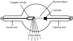
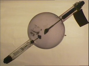
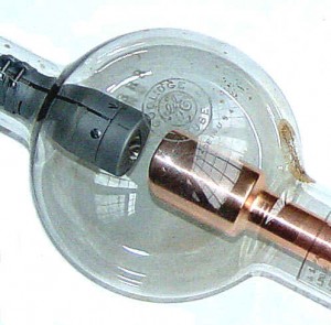
The disruptive discharge, wrongly called “spark” is not for transmission work. This oscillatory transient wave is for Aether work. Today this is reduced to plasma work. Here is where to find the Tesla X-Ray research. See E.P. Phenomena of the Anode and Cathode.” Transmission applications utilize continous waves which may be complex harmonic formsas well as simple harmonic functions called “Sine waves”. Individualized harmonic structures gave “channelization” to the Tesla Transmission Plan, this analagous to carrier telephone multiplex systems. Tesla called this “Individualization”.
It is very unfortunate to hear that you live in the U.K. This is the land of George Orwell. His 1984 was reversal of 1948, his idea of the birthdate of human hell on earth. U.K. is very unfriendly to radio, actually it despises it. I would be imprisoned for my military Corolla, and they would destroy the car. But here in America the car is a registered civil defense asset to the Sheriffs Office.
Quite a disparity would you not say. It will be here in America soon, we fought this at Camp David. In the desert it was said “First your guns, then your radios”, the united way.
I grew up in the world of 300 Kc to 3000 Kc, at one time it was a vibrant band of aeronautical and maritime activity. This now is mostly a wasteland and the broadcast band is now no better than C.B. radio. The maritime service allocations near 500 Kc are now open for an engineering development of an improved system for the transmission and reception of signals for ships at sea. This was the mission set upon me by the Radio Corporation of America. This is one place to start a Telluric Broadcast Beacon to ships at sea, it is licenseable.
The other angle to take is Industrial, Scientific, and Medical. Every country uses induction or dielectric heating equipment. It was my job in Los Angeles to rebuild the 10-100 Kilowatt units and in some the stray fields were scary. These often use power oscillator of poor frequency stability thus have their own allocations often away from other services. In America one frequency is 400 Kilo-cycles. However these frequencies are not intended for communication purposes, only its scientific development.
Therefore, in order to begin one must directly contact, in person if possible, the radio commisar of the country which a setup is to be established. Also someone must have a commercial radio license in most cases.
Finally there is the 160 meter Ham band but the Ham band is like the city Greyhound station, Bengal. Most Hams today are walkie-talkie yac-yackers, they have no interest in radio so that leaves 160 meters open for experimentation.
Ultimately it is the International Telecommunications Union, Geneva, that decides and dictates radio law. Radio is government controlled in accordance with I.T.U. guide lines. The principle countries in which Telluric Transmission Systems are culturally relevant is USA, UK, and “down under.”
With these considerations the first step is post the basic I.T.U. guidelines for frequency allocations. Then post the band allocationsfor USA, UK, and Japan. This data in one place would be very instructive.
73 DE N6KPH
Post numbers here refer to the Crystal Radio Magic Thread
Post 73, Jake.
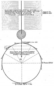
Standing wave on coil indicates proper operation. A voltage node must exist exactly at the neutral terminal. Tesla could move this node about in the earth. This is important and in an optimum state the voltage node is right at the point of earthing. A projected wave velocity exist on the earth surface, infinite at the earth connection, and luminal 90 degrees around the planet. It is a tangent function with Pi over two as the “Effective velocity”. Hence velocity here is only a projection on the earth surface, not a true velocity, like your shadow at sundown it goes to infinity.
Post 136, Madhatter.
The B field is a bad way to look at this. It is a physics dingleberry. B is a dimensional relation with a per centimetre square. Here it is best to use versor magnetic induction k Phi, see last part of Theory of Wireless Power. Mutual inductance is longitudinal so that coupling remains for concatenated longitudinal resonators. Wave direction now has a role in coupling.
Post 143, Madhatter
Wave direction coupling makes balance to unbalance transformation impossible, this gives the “dead phase” extra coil. If it is a balanced system, every part of that system must be push-pull. Unbalanced unit has neutral on one side of primary, a balanced unit has neutral on primary center tap. All concatenated coils must be wound in same direction as wave propogation spiraling around them.
Post 156, Jake
Do not replace 100 pF condenser with LED, it will distort and rob power from the audio. Use a completely separate setup for LED. Try Ne 2 neon lamps. Also a 10-15 watt fluorescent lamp is a good standing wave “wand”, this for tuning.
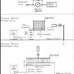
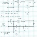
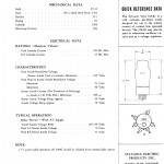
I would recommend using a 6SN7 Triode section with cathode drive from function generator and the primary as the plate tank circuit. See the figure. This will greatly improve resonance for tuning. 50 Ohm across primary NFG, 6SN7>6000 Ohm general.
Multiple tuning peaks indicate overly tight coupling between coils. Slowly separate them until only one resonant peak. Multiple modes of stray reception and strong local stations will make grounding and tuning very confusing. An isolation amplifier 6SN7 triode isolates amplifier from function generator interaction and gives more power to light neon lamps. Both sections of 6SN7 in parallel give more power.
73 DE N6KPH
Eric does not buy the “Eric causes his own problems”, that is a stock statement. The fact remains that Tom Brown, in conjunction with a wicked female (to say it mildly) kept the money Reynolds sent to move the “Cosmic Lab” from Santa Barbara. This is a fact Mr Brown. The shipyard had to come up with the money and place to move it to, where it finally was lost when the business closed there. Also the Franklin family who owned Camp David say you got them to sign over their land and that you then sold it from under them. And all that common law crap got David in big trouble, how he cannot drive a car and went insane after Camp David went under, good work Tom. And for what, to feed a witch intent on bringing evil to the earth. Looking around at the horned female archetype rampant I say (She) did a good job.
Eric’s problems arise more from the wicked female hate of the “feral male” than almost any other source, and her fabricated cover stories do not cut it anymore. None of it does, the numbers speak the truth. QRT on this matter, not the best use of the forum.
F.U. DE N6KPH
For the next few days I will have direct contact with the “Internem” and can communicate via this forum. It is split now off into T.M.T. Replication, and Crystal Radio Magic, but I will stay on this channel for simplicity.
I am not sure on Colorado transformer info thus far given, the extra coil is not square. It would be nice to see the pages referenced displayed here. My aim is to make all this pictorial, with few words. Pictures, diagrams, and equations are the language of engineers.
I recently read a copy of M.W.O. Handbook (Lakhovsky) and seeing my antenna design being used without a bit of compensation, and moreover improperly connected. This re-lit the Borderland Tom Brown fire. It should be pointed out that the creation of T-rex came about when my Corolla’s patron ran across the forum. He had spent a lot of money on the “Lindemann crowd” and then produced nothing that works and copied my ideas. The battlefield is set, but I chose to remain more scientific and less a vicious combatant. Since it is now being said that it is my own fault, this and that, including Landers, I have decided to write an entire series on my “Borderland” experience.
The purpose for getting hard core on legalities is that we are not playing with cardboard tube junk spewing sparks anymore, nor Meyl toys. These networks I am presenting are actual transmission devices and can be dangerous in that they give rise to waves in house wiring that can start fires. My high school years lab allowed me to pull a 3 inch flame off the screws on the garage light switch and the patio lights came on with the switch open.
For Madhatter, the book by E.P. Thompson, Rotgen Rays, and phenomena of the cathode and anode is a must. Via this book I isolated the Aether element (pre Hydrogen) Coronium. It has a living green green color when excited electrically. I used an unbalanced disruptive setp and duplicated many of Tesla’s claims. This was just a Pri:Sec setup connected like that I just put out here, but no switch, but a spark gap in a renewable 400 amp fuse.
The inductance of coils in a Tesla Transformer has no meaning, they are waveguides not inductors. Can someone print here the pages from “Theory of Wireless Power” that give equations for velocity, impedance, etc. Then these can be applied to everyone’s unit and Tesla’s at Colorado Springs. Let us try to assemble a compendium of everyone’s efforts and include Tesla’s Colorado Unit. Hereby science can be turned into engineering, this with a minimum of Babylon.
K DE N6KPH
Your extra coils should be on the ends of the secondaries, not separate. Do it as in the picture below:
Make sure the winding directions are completely opposite on both sides. You have a kinked standing wave. The node is not in the middle. Might have to balance out the coupling. Everything must be equal and opposite on both sides otherwise they won’t balance. The two primaries should be in series and connected to a common capacitor. And the center tap connected to neutral. That’ll help.
When are you going to hook it up to a multipactor tube? Farnsworth said a
balanced multipactor tube and Tesla coil are a “marriage made in heaven”
Theory of Wireless Power Equations:
All equations here will work with everyone’s coils. They have been tested experimentally and are known to work.
Reference Download -> Pg. 28-34 of The Theory Of Wireless Power
On this last page the values listed in table 3 are wrong. They need to be recalculated from the equations in the text.
If T-Brown is such a sweet heart why do so many here in America despise him? If I multiply everything by k, then I do cause my own problems, since as a “street person” I invariably get involved with criminal, violent, or mentally deranged people. And since I have no recourse they turn around and take me for a ride. This will never change, Roy Stolti and Landers, Eric Johnson and my dog, etc, etc. This is the American way of doing business Edison States, take what you want without regard and then violently lie about it. No more on this.
QRT DE N6KPH
The writing “Tesla’s big mistake” is a misrepresentation of Tesla’s work. The diagram shown has nothing to do with Tesla, but is actually a strange wave called a boundary wave. Ernst Guillemen discusses this in the introductory chapter of his second volume of “Communications Networks”.
73 DE N6KPH
A circular waveguide is a linear system it does not generate sidebands. What it does do is there’s a mode called TE02 which exhibits some extremely bizarre propogation characteristics and defies excitation. If a circular resonator is brought into a complex oscillation it will produce an un-musical enharmonic series, much like the waveforms produced by a drum. No log periodic series exists here.
73 DE N6KPH
This question appeared here on the E.G. forum, Peter, Whatever happened with Eric Dollard? He has just vanished like a fart in the wind. Why?
Someone arrived in Lone Pine from the Annenburg Foundation. He was sent to talk to Eric Dollard. This person tickled my ear with great promises, golden futures, and how I was such a wonderful discovery in his life. He tells me that he will take my driveshaft into safe keeping. Both him and the driveshaft are never to be seen again. And it is said Eric brought it on himself.
This is the life story of Eric P Dollard. And of course, Eric always brings it on himself.
A person shows up at Landers, he “wants to learn” from me and “help” run the station, so he says. Once inside the story changes and I am harassed out of my own installation. His pit bull horns my female coyote and 7 puppies show up at the wrong time. The station turns into his hell hole and Olin Bales finally got it.
The story is the same again and again, Eric just keeps making his own problems. True, by involving myself with humans.
A scientific analysis would be massive and is beyond the scope of this E.G. forum except maybe the “American Ruling Class” group. I look around me and see a nation of absolute swine, disgusting human filth, arrogant blobs of putrid pork resin thrusting about in 6 wheel trucks with a homicidal rage. Emblematic skulls and axes abound on every surface. It is a nation of death.
What you see of my efforts on this forum is the product of two patrons: Captain Don Hughes, and R. Joshua Reynolds. Captain Hughes supported all the Symbolic paper writing, now on the internet, and cemented me into lifetime employment in the S.F. Bay Maritime industry and provided me with a Navy ship. Freedom from the dumpsters. Josh Reynolds funded my aquisition of the Corolla, an important improvement in my life, now I could find work and had a definite home, like a tiny Navy ship. Freedom from the C*nt. These two important individuals are both dead now, there are no more like them on earth anymore, they went the way of the type 80 rectifier tube.
Ultimately it is only the papers and the Corolla that have survived. All else is gone. The loss at Landers is overwhelming and has left me disabled. Now why would I want to engage in another “Help themselves to Eric Dollard”. So this is what ever happened to Eric P Dollard.
73 DE N6KPH
Mutual Inductance is a strange problem. This term is a depository for many notions, and has been my biggest dilemna in formulating a four energy travelling wave equation. I solved this at Landers in an analog form, but I am unable to recover my notebooks, yes the someone showed up to help Eric again. (Think that’s how the PRC-47 from Landers came up on e-bay, goood buddies don’t you think?)
To use reluctance as an expression for mutual inductance is not such a good idea. In a way this is like equating reactance to resistance. Mutual inductance evokes a space quadrature relation, a space versor. Examining the inner workings of a transformer is helpful in conceptualizing mutual inductance. In general mutual “Enductance” exists outside the windings, self inductance exists inside the windings.
It is postulated that magnetism is a flow in the Aether. This flow defies normal conceptions of space. Associated with this flow is Faraday’s electro-tonic state, a primordial idea of electro-motive force. The notion of electro-motive force is no less mysterious today than it was in Faraday’s era. Maxwell was really of no help either, and today’s parrots sing the tune. And to make this even more complex is the electronic interaction. We can form no picture of “Magnetism” and it is futile to know of its ways by throwing more equations filled with quaternions and partial derivatives at the mystery. An entirely new direction must be taken.
Relating magnetism as a flow, i, in Amperes, expresses its force. The total quantity of it is given to be the total number of lines of force, Phi. But what lines of force, what do they look like, can I see one on youtube?
No matter what direction is taken soon the barbed wire grabs hold. Somewhere between J.J. Thompson and C.P. Steinmetz is the answer as to what is a line of force. Steinmetz says that there are ten to the 8 power of them in one volt-second, and hence it can be said that one individual “strand” is a unit Phi, or line of magnetic induction. Volt-second is “magnetic charge”.
Mutual enduction exists in a counter-spatial relation with self induction. The two are space conjugates. Here defined is each,
1) Self induction, L, Henry
2) Mutual Enduction, M, per Henry
L represents space and M represents counterspace. M is a form of “magnetic capacitance”. The more space between the wires, the more L exists in Henrys, the less space between the wires the more M exists in per Henry. These two quantities are mere reciprocals, that is, until they are differentiated.
The dimensions of L is centimeter square and the dimensions of M is per centimeter square. The dimensional operator or first order derivative is the dimension of per centimeter. Hereby dimensionally for distributed constants the distributed inductance is Henry per centimeter, or just centimeter, and the distributed enductance is per Henry per centimeter, or per centimeter cubed. These dimensional relations establish the travelling wave of magnetic inductionin the metrical dimension of space, LM. The dimensions of this travelling wave of induction is LM equals per centimeter square or a second order differential in the metrical dimension of space. This gives rise to a hyperbolic function with respect to distance along the propogating structure such as a transformer winding. Th square root of LM is the hyperbolic angle, Nepers per centimeter.
Exactly analogous conditions exist for the dielectric field, where the propogation is now given as CK. Both LM and CK are here given on a per centimeter basis. That is now L is Henry per cm, and etc. While this is customary the distinction is confusing. Lumped constants, and distributed constants are not the same dimensions. Further compounding the confusion is that the permeability, Mu, is also dimensionally in Henry per centimeter. It is a Labyrinth! Break, more to follow
The dielectric field exists as a conjugate relation to the magnetic field. Like the magnetic field it can be expressed is self inductive and mutual inductive components, these in a space vs counter space and space quadrature existence. Here given is the self capacitance and a mutual elastance. In general the self capacitance is outside of the winding space, and the mutual elastance is inside the winding space. As with magnetism here is a space versor.
It is postulated that dielectricity is a tension in the Aether. Again it seems to defy notions of space, such as if a line of force has no broken end in space then how can it propogate? It cannot propogate if it did not already exist. Another bottomless pit. Associated with this tension is a displacement current, a notion of Maxwell, but it is like EMF, it is an idea. Relating dielectricity as a tension, e, in volts expresses its force. The total quantity of dielectricity is again considered to be the total number of lines of force, Psi. What lines of force.
The trap is the same as that encountered with mangetism. J.J. Thompson seems to think there are 1000 of these lines of force terminating upon todays electron. The electron hence contains 1000 Thompson Aether corpuscles. Heretical! Here the quantity of dielectric induction in lines of force is given in Ampere-seconds and this established their number as the “dielectric charge” just as the Volt-secind defined “magnetic charge”.
Self capacitance is in a counter-spatial relation with mutual elastance. The two are space conjugates. Here defined is each,
1) Self Capacitance, C, Farad
2) Mutual Enductance, K, per Farad
C represents space and K represents counter space. K is a form of “dielectric inductance” but not in the same way as L & M. Complications exist here in description since magnetism is intrinsically spatial and dielectricity is instrinsically counter spatial. It is not so easy to just “step through the looking glass”.
The two quantities are reciprocal relations, one is the inverse of the other, again, until differentiated.
The dimensions of C are one over c square (the “hand” on the monochord). This is thus second square over centimeter square and hence the dimensions of K are c square or centimeter square over second square. The dimensional operator or first order derivative is the dimension of per centimeter. Hereby dimensionally for distributed constants, the distributed capacitance is Farad per centimeter or second square per centimeter cubed, and the distributed elastance is per Farad per centimeter or centimeter per second square. Denoting now, as with the magnetic component, the distributed capacity as C and the distributed elastivity as K, the travelling wave of dielectric induction in the metrical dimension of space is CK or per centimeter square. This is a second order space differential. This gives a hyperbolic function with respect to distance along the propogating structure. The square root of the product of distributed constants, CK, is the hyperbolic angle, or propogation constant, Nepers per centimeter.
Considering now both fields of induction, the magnetic and the dielectric, there exists a pair of propogation constants, the square root of LM, the magnetic propogation, and the square root of CK, the dielectric propogation. Both distributions are a hyperbolic function of distance but now cannot properly be called single energy. Both the magnetic and dielectric propogations are time scalar, no time delay exists but the distribution in space is instantaneous. It may be postulated that the mutual magnetic and mutual dielectric components L and K are not affected by metallic obstruction but now the metallic is rather a conduction through its counter spatial dimensions. Break, more to follow
Previously defined are four dinstinct electric types of inductivities:
1) Self inductivity, L, in Henry per centimeter
2) Self capacity, C, in Farad per centimeter
3) Mutual enductivity, M, in per Henry per centimeter
4) Mutual elastivity, K, in per Farad per centimeter
The dimension relations are given as:
1) L, centimeter
2) C, second square centimeter cube
3) M, per centimeter cube
4) K, centimeter per second square
These are the distributed constants of the generalized field of electric induction. The two distributions in space are defined by:
1) LM, per centimeter square
2) CK, per centimeter square
Dimensionally standing between LM and CK is the dimensions of second square. This is to say that the magnetic distribution and the dielectric distribution are interwoven through the dimension of time and its relation frequency. This is not unlike a simple condenser and reactance coil which interect through per second square. Now the two fields are not lumped, but are distributed in form. Hence the time dimensional interactions between LM and CK gives rise to a complex of electric wave propogations in both spatial and counter spatial modes.
Here we meet with the completely generalized electric wave. We are nearing the holy grail of electrical engineering.
The complex of magneto-dielectric interactions can take four distinct forms. Each is a single magnetic energy interacting through time with a single dielectric energy. Hence:
1) LC, Henry-Farad per centimeter square
2) MK, per Henry-per Farad per centimeter square
In dimensional expression these are given as,
LC, second square per centimeter square
MK, second square times centimeter square
These two terms give rise to a pair of propogation constants,
One over the square root of LC,
1) centimeters per second
One over the square root of MK,
2) per centimeter per second
Relation (1) is a velocity, motion through space over time, and relation (2) is a counter velocity, motion through counter space over time. These two propogation constants represent the motion of electric induction in a general metallic-dielectric geometry. Unlike the distributions LM and CK which are hyperbolic functions of distance, the propogations LC, and MK, are circular functions of distance along the propogating structure. It can be said two hyperbola are transformed into two circles, this as a geometric analog.
Two additional interactions between magnetic and dielectric inductions arise,
3) K/L, per second square
4) M/C, per second square
or alternatively
3) L/K, second square
4) C/M, second square
A reciprocal relation suggests itself here such as
3) L/K per second square
4) C/M second square
In all their forms both L over K and M over C are space scalars in that they exhibit no distribution in space, everywhere at the same time. Relations (3) and (4) are space-scalar frequencies of magnetic-dielectric exchange and accordingly they are circular functions of time.
Through the presented dimensional relations a generalized expression for electric induction is established. It consists of the following components,
1) The space distribution of magnetic induction, LM,
2) The space distribution of dielectric induction, CK,
3) The time rate of energy exchange between self inductivity, L, and mutual elastivity, K,
4) The time rate of energy exchange between self capacity, C, and mutual enductivity, M
And these four factors, or constants give rise to a pair of electric wave propagations,
a) The electromagnetic propogation in space, LC,
b) The magneto dielectric propogation in counterspace MK
Here four scalar constants, two time scalar, two space scalar, give rise to a pair of waves in two conjugate dimensional relations. This is a bit more complex than a single lumped condenser, or a single lumped reactor. In fact in view of this more generalized understanding the condenser is in actuality a mutual elastor, K, and the reactor is in actuality a mutual enductor, M. Here is a completely reversed viewpoint.
73 DE N6KPH
There seems to be little progress in the longitudinal moon bounce idea, this because we do not know what it is that is bouncing off the moon or if it even bounces at all. It seems necessary to go back to “square one”.
It was said that you cannot see the stars in outer space. Is there some reason why you should see them? If then there is no primary light in outer space beyond the influence of the earth then there is no velocity of light since there is no light. This is to say there is not a delay in time when viewing objects in deep space, no light years, etc. The distant galaxies then appear here just as they are, not images of a distant past. Relativity crashes into oblivion. What is known on earth as light is electro-magnetic waves. These light waves of course propagate at luminal velocity.
The sun and stars in this view emit primary induction, not electro-magnetic waves. This is to say that while man made waves that take 8 minutes to travel from sun to earth, the primary induction of the sun arrives at earth much sooner, if not instantly. It is the envelope of the earth itself that engenders the sun light. Through a better understanding of this primary induction a transmission system utilizing it can be developed. The idea here is NOT to get too hung up on theory and innumerable details but to make something work, and this is in the face of impossibility. This is like a military situation, make it work or the ship sinks. The Navy has no secret Telluric system, and moreover they gave up on E.L.F., 76 cps.
Marconi just does not work at those frequencies. If there was such a Navy Telluric transmission, it would be received at Landers. The Landers antenna was capable of detecting underground nuclear detonations, and the Navy 25 Kc/sec fleet broadcast was overwhelmingly strong, requiring the use of band reject networks. Break, more to follow
The four field diagrams of a pair of round conductor, 1/4 inch diameter, 3 inch spacing need to be produced here,
1) L, 100 Ampere in opposite directions in each conductor
2) M, 100 Ampere in same direction in each direction in each conductor
3) C, 10 Kilovolts, same polarity on each conductor
4) K, 10 Kilovolts of opposite polarity on each conductor
The diagramatic superposition of each of these flux diagrams with its various conjugate flux diagrams will give the patterns of LC, MK, L/k and M/C. Who can do this? It is important here!
As for the moon bounce, there are a few starting ideas of practical construction.
1) The Integratron, a Caduceus space scalar oscillator and regenerative detector,
2) The log-periodic M.W.O. as conceived and operated by E.P. Dollard,
3) An isolated extra coil excited by magnetic uni-directional impulses from a hydrogen thyratron radar modulator,
4) A particular waveguide mode coupled through a transverse mode suppresor into space,
5) An Alexanderson type flat-top structure.
Items (1) and (2) are a U.H.F. antennae form of geometry. The Caduceus is expected to produce a space scalar transmission between identical units, like an Integratron on earth and one on Mars, the log M.W.O. is a space wave structure and transmission between antennae is an easy experiment, if you can find a pair.
Item (3) is a dialectric impulse projector and will produce the pure dielectric translation through space, it cannot be a wave, it is like CK, hyperbolic. (See Steinmetz “lightning wave”)
Item (4) is an end-fire and item (5) is a broadside, longitudinal electro-dynamic transmitter. (4) is end to end transmission between units and (5) is side by side transmission, face to face, between units.
Only items (2), (4), and (5) are useful with a reflector antenna, impulse and scalar cannot be reflected since no “wave” in space exists. This makes a moon bounce hard to conceive in a normal sense, maybe an E.M. wave will come back, as a secondary.
Note C.R.I. :
As for the Telluric vs ionosphere velocity differential, this using the detected audio signals of the A.M. broadcast station, one receiver goes into the scope vertical the other receiver goes into the scope horizontal. No time difference is a 45 degree line, a quarter cycle lag/lead is a circle. It is important that the luminal receiver have no neutral and be on a balanced dipole antenna, cut in middle and as long as possible. This can be coupled with the radio loopstick by putting another coil on this loopstick like a transformer.
It would be nice if someone could post a diagram of a radar modulator with a 5C22 hydrogen thyratron and a Guillimen network. (See MIT radiation laboratory series.) The Integratron coils were a caduceus pair of flat spiral coils, 90 turns each and about 50 feet wide. Each coil used about 5000 feet of wire, one 10 gauge copper, the other 14 gauge iron. The women in white ripped these windings out when they seized the Integratron, at Landers California in the mid 1980’s.
Finally, on the hand of god tuning the monochord. It was considered in certain experiments with Navy sonar crystals that one over c square is not constant. These crystals would charge to powerful levels, 5 kilovolts at .015 microfarads, just sitting on the table. The position of the moon played a significant part. If the luminal “velocity” varies, then its dimensions of capacitance, one over c square varies. Capacitance varies as the speed of light. Therefore a static condenser will produce small displacement currents during variation. This was done at Landers with Chris Carson and myself, putting the variation of potential on a chart recorder. This is an area of further experimentation in “primary induction”.
73 DE N6KPH
—-> Famous Scientific Illusions by Nikola Tesla <—–
I ran across a Tesla article title “Famous Scientific Illusions” while looking at electrical experimenter magazine (Hugo Gernsback). This article is hard to read but contains some extremely important insight into Tesla and his efforts! This article should be re-printed and presented here in an easy to read form, very important.
The radar paper by Lt. Commander G Brown is very instructive. The Gullimen line is a very complex subject. Two of his “Communication Networks” relates this subject to analysis, but it is hard to understand. I was reading this when I was working on the Navy LCS-102 at Mare Island a few years ago but my life again was violently disrupted and the book was lost.
I had constructed a few line/thyratron modulators in Santa Barbara, these can be seen in the first Borderland video. Three videos which are now well known as well as 8 U.S. Psychotronics Association lectures in L.A. which are lost, were produced with the funding available. Since no “free energy fusebox” was invented the funding was withdrawn. Much effort was spent on moving this equipment about, as previously stated, and eventually disappeared. The radar transformers and network vanished along with the cosmic inductorium.
What is needed from the M.I.T. book is a detailed diagram or schematic of a line type hydrogen tube modulator. One with the 5C22 thyratron and 705 diodes is best. Also the four field diagrams L, M, C, K, I asked for are of the ultimate importance. Who will do this?
Madhatter (multipactor) has noticed that his “dead phase” extra coil jammed his “silly phone”. I have noticed similar strange effects. Strange things lead to strange discoveries. Is some kind of “space scalar” effect showing itself here?
Do not be fooled by George Gabory of the SF Tesla Society. The videos are fine and need no edit. The one on youtube is a backup copy made in case the inevitable happened, and it always happens, guaranteed.
He and his group have no interest in my work, nor that of Nikola Tesla. They are onyl interested in the prevalent Commonweal agenda of the SF Bay area.
I attempted to enlist their help with Landers based Mojave Research Station, at least to document it. They showed up to glom “free energy secrets” but there were none. Yet they spent an untold fortune defending Paul Pantone. Useless!!
Any attempt at recovering the Landers notebooks has failed. These were taken by Roy Stolti, someone who came to “help Eric”.
I have come to the conclusion that all this misfortune originates with the “girls” at the now defunct Integratron. After starting a fire they attempted to commandeer my Mojave Station once and were cutting into my telephone lines. So what does that tell us. Who is going to help me next?
73 DE N6KPH
5-C-22
5 first, C, second, 22, third
First number, cathode power category.
1, no cathode
2, small cathode
3, typical cathode
4, larger cathode
5, large cathode, etc.
8, giant cathode
Second Letter
A, one element (light bulb)
B, diode
C, triode
D, tetrode
E, pentode
Last number, individual tube type in series
The 8D21 is a giant 3E29, 9C21 biggest tube in series
Phase Shift Determination by means of an oscilloscope (C.R.I.):
Gabriel Kron sits somewhere between Heaviside, Steinmetz, and General Electric. Tell us more about him.
73 DE N6KPH
Let us look at the year 1919. World War One has just established the “New World Order”, part one. Franklin Roosevelt, assistant secretary of the Navy has successfully outlawed radio in the USA and Tesla is history, he has no possible hope of ever regaining a suitable laboratory in which to carry out his work. His only recourse is to irritate the A-holes with a string of magazine articles. It was great for Hugo Gernsback and his magazine. This just like Eric Dollard on the Energetic Forum, identical.
Tesla, in his famous “Scientific Illusions”is behaving like a coyote. By interweaving the known scientific conundrums with his own Telluric Radio System, he gets a stab or two into the flesh of G Marconi. However Tesla is a bit one sided in this and gives an unbalanced account of radio in general. Tesla’s system is V.L.F. 3 Kc/sec to 30 Kc/sec. Forget the Earth-ionosphere waveguide, he shows that is does not exist in his drawing, all one sixty-fourth of it. But Tesla makes a faulty claim that all radio must be Telluric. This is not true. By 1919 Marconi was kicked out of the USA for ripping off the US Navy (1917). R.C.A. was not yet born so J.P. Morgan’s General Electric took charge of the Marconi Installations, hence Steinmetz and Alexanderson rebuilt these stations (KET Bolinas and WII New Brunswick). In retaliation Marconi developed short wave radio, 3 Mc/sec to 30 MC/sec. These waves are not Telluric but are ionospheric. Here then is an “Earth-Ionosphere Waveguide”, but not at V.L.F. Tesla is correct about the extreme attenuation of the ionospheric mode in his article for the Electrical Experimenter. A billionth of a watt is now correct, but the Armstrong Regenerative Detector came to pass and it has infinite amplification. David Sarnoff took this invention far, from Marconi to R.C.A. (see PBS video “Empire of the Air”).
So Tesla misinforms his readers to emphasize the singularity of his Telluric System. In my opinion Tesla’s later articles were for spitting in the face of his enemies. His later claimed discoveries are most likely re-statements of his 19th century work.
73 DE N6KPH
The “Landers Antenna” was a tandem pair of an Alexanderson Antenna (Earth) and a beverage antenna (sky), this is the earthquake system. This was constructed on the land of Walt Deroche, a retired Aerospace worker. This system was developed long after the Sheva forced me and then Lockwood out of the Integratron. The Sheva strongarm George Riddle tried to grab my laboratory at the Integratron but failed (we had guns too!). This gear became the lab seen in the Borderland videos. The Sheva stripped stripped out and scrapped everything Van Tassle put there including the “Ceiling Coils”. Later they put up their own coil improperly, and then spread rumors that ” I would burn down the dome” when they finished it, which of course they have no intention of doing. The Landers Antenna came about after I lost the Integratron to the Sheva. It is unfortunate but I do not remember its makeup and Roy Stolti will not respond to requests for the return of my notebooks. This is the earthquake system, not the Integratron.
The Sheva, and its component the “thing” that took over the mind of Tom Brown and Borderland works to bring a female Satan to Earth. This is also the primary objective of Commonweal in Bolinas, CA. That destroyed most of the RCA station there.
The Caduceus Coil is as drawn in diagram, notice the polarity dots, two coils wound opposite upon each other. Van Tassle says the wires of the conjugate coils should cross at 22.5 degrees. A 16th order versor is an important factor underlining all of George Van Tassle’s efforts. Also his relatives claim that a second wife Doris killed George, and later she was drugged to help get the Integratron away from Lockwood.
73 DE N6KPH
In “Travelling Waves on Transmission Systems” by L.V. Bewely, the section on transformer waves has equations relating to the calculation of L, C,, M, & K.
The four field diagrams I asked for are of EXTREME IMPORTANCE, is there not some computer program that does this? Also it might be time to re-collect in one spot the initiative to find equal and opposite forces on the LA D.W.P. DC power line. This is also important here again.
The test loop coil for the C.R.I. tuning is 14 gauge wire for 50 Ohm and 18 gauge for 500 Ohm test oscillators. Same diameter as coils being tuned and a minimum of height, the turns tied together. A 6SN7 or 6V6 vacuum tube amplifier after test oscillators may help.
Orion, post 492 shows a setup by Russian engineer Avramenko. This information is the final confirmation of my observation and theory that the Quadra-Polar self resonance of a coiled metallic-dielectric geometry is a true single phase, or monopolar transformer. Again the critical question rears its head; does a displacement current produce a magnetic field in the insulator which “carries” this displacement current. This is also of extreme importance.
My understanding is that Faraday regarded the dielectric, or “paired electrics”, to be the seat of both magnetic and dielectric induction. Hence the term dielectric field may be a bit misleading. Now we are relating the product of Mu Epsilon, a dipolar, and it can hereby reasoned that the iron core is in actuality a dielectric medium that acts upon Mu rather than Epsilon. Strange is the seeming requirement for a continuous metallic path for the magnetic current i, for mutual “inductance” to take place between windings. Ferrites, more like a “dielectric” than sheets seems not to work for H.F. Hi-Z transformers. A 4800 V:120 V step up is impossible at 10 mega cycles.
Chris Carson and myself produced a Caduceus coil oscillation setup and it began to exhibit some space scalar effects. It was connected as shown in a previous diagram. It was connected as shown in a previous diagram but using a small 6J6WA double triode. The frequency was remarkably stable and unexpectedly high, V.H.F. But Chris died and I forget the tube connections. Receiving signals from another dimension was my understanding of the Integratron. See Outer Limits, first T.V. episode, “Galaxy Being”. The Russian parametric paper discusses vacuum tube parametric oscillators and these have very very interesting characteristics resulting in unusual modes of reception.
Finally, the Multipactor tube. The Farnsworth family was less than cooperative in helping me understand the Multipactor tube, and it also exists in a wide variety of forms. Philo was very interested in a symmetrical tube/symmetrical Tesla Transformer connection but Philo was also insane by the time I met him, when I was a human rat eating out of dumpsters. Here is what I know:
The big complication is the cathode coating. High emissive currents burn it out and the coatings are extremely difficult to form. Cathode burnout seems inevitable. Farnsworth’s efforts developed out of Einstein’s famous 1905 paper on the photo-electric effect. He was not into writing books but had his hard bound notebook series (Gone!). I read part of it and saw many tubes, but Commonweal stole some of these from Philo’s house. What I noticed is that the so called grids separated the electrons from their lines of force, but who’s electron, JJ Thompson’s or A. Einstein’s? That I do not know. By the way Tesla used aluminum for his beam tube cathodes. Aluminum is a good secondary emitter and the oscillatory transient will cause Multipactor action. Did Tesla know this, he did make thousands of non-thermionic vacuum tubes. Also note W. Crookes is the inventor of the vacuum tube, find more on him.
73 DE N6KPH
Flux Diagrams – Post via jpolakow:
Eric really stresses the importance of having these field diagrams. He is hoping someone can computer generate them. He would like to see each field separately, so they can be superimposed on each other. I’m trying to show exactly what he would like to see.
In this first diagram, we have just a schematic of the lines of force around a pair of conductors for L, M, C, and K. These are not the flux diagrams, just a representation of the relationship of the lines of force and the pair of conductors(square).
Here we have displayed the self inductance, L, and the mutaual elastance, K. In this diagream the Magnetic lines of force are repelling the conductors, and the Dielectric lines of force are pulling the conductors together.
Then here we have a diagram that is like(not the same as) the representation of C and M. The lines will be similar but different. It looks like C and M, its not the same thing as C and M, but the lines are the same shape.
From Elementary Lectures on Electric Discharges. Waves, and Impulses, and other Transients, Steinmetz:
This is K, Mutual Elastance, Attraction
C, Capacitance, Repulsion. Repulsion is attraction to a distance, grounded infinity
Eric would like to see these diagrams for the constraints given for the conductors, spacing, voltage, and amperage given.
The coils were deliberately designed to be high in frequency. Once the secondary is fully interconnected it was expected the frequency would drop. A large air capacitor called a neutralizing condenser is to be connected from the secondary to neutral by broad surface(conductors) as a tuning capacity. This helps in tuning the whole system up.
73 DE N6KPH
The 30 notebooks most of which was funded by Captain Don Hughes, were kept at Borderland for safekeeping. As told to me by Mike Thoreux, that Tom Brown and the “Thing” deliberately jettisoned all my material so the notebooks have vanished to the winds etc.
KVOS Webster Reports: The Extraordinary Equation of George Van Tassel – YouTube
In this video George Van Tassel speaking about his experiences with Aliens at the Integratron. This is an extension of what I’ve been talking about.
73 DE N6KPH
The Tesla Transformer is only a component, such as a resistor or condenser. A simple condenser can force an A.C. wave out of existence, but it can also magnify it to enormous magnitudes. The Tesla Transformer is an impedance to admittance converter. It can also be a phase converter from conventional bi phasic currents to, or from, monophasic currents.
A dielectric translation through space is not a wave. Ultimately it is uni-directional, no magnetic field is expected. See the writings of Vassilatos in “Secrets of Cold War Technology”, the Tesla chapter.
The longitudinal analog network that I made known can do some of what the Tesla Transformer can. Later on I came up with a more advanced plan resulting in a complete lumped component network equivalent of a mono-polar transforming Tesla Transformer but that work is now lost. Mutual Inductance is the major complication, as has been recently discussed here. For the most part a simple series resonant circuit of very large inductance and minimal capacitance will produce the results sought after in a specific engineering application. This series circuit, a form of M/C network must be driven by a constant potential source of negligible internal impedance in order to get full magnification and rise in output potential. It can be dangerous.
73 DE N6KPH
Faraday did not have a computer and knew not of volts and amps. But Faraday did have iron powder. Something like Lycodium powder was used for the dielectric, see dust types of Lichtenburg patterns. A current based program is fine, 100 amps, one fourth inch, 3 inch spacing, one for opposing, another for aiding. Through the cross products of L/K and C/M the equipotential lines are defining the dielectric lines. This can be seen in the figures thus far provided. A field map can also be integrated from magnetic and dielectric compasses. Maxwell describes field mapping in his book.
73 DE N6KPH
After looking at Van Tassel talk on the old black and white, my interest is a bit renewed in this enigmatic apparatus.
I had spent 2 years in the direct study of the Van Tassel Integratron, from a hands on position. Lockwood and myself had managed to restore the installation which Van Tassel operated in Landers, California. It was brought back into the form in which it existed at the time of Van Tassel’s death in 1978. His second wife Doris furiously opposed our efforts for some reason and they say “she killed George”. By good fortune his son in law, Daniel Boone, who was present at the visitation by the E.T., was very helpful. I had developed the notion that providence provided the union of E.P. Dollard and D. Boone in order to bring the Integratron to life (about 1984). Other people had a different plan so now it is just another conspiracy story at best. Today the installation is disfigured, all technical apparatus gone, and operates as a self worship temple for the “divine Sheva”. So what is new, just like RCA Bolinas, etc.
The Integratron operated in the following manner:
Three basic components made up the Integratron.
1) A rotating Di-Rod electrostatic generator which encircled the main deck of the Integratron the projecting aluminum studs are the parametric condensers to energize it, 100 Kilovolts DC out.
2) An electro static condenser consisting of a large wooden hemisphere with an interior aluminum leaving. This was charged to 100 Kv.
3) A large Caduceus transformer of flat spiral form wound upon the ceiling of the transformer, or lower deck.
The armature was to be driven by compressed air rolling on a massive integral roller bearing of teflon rollers and races.
Because compressed air can be sent through pipes of dielectric material this served not only motive power but also control air. Four air driven mechanical switches around the periphery alternately engaged the charged dome and the transformer windings. The opposite ends of the windings capacitively terminated on a hollow central core where a special network would be lowered into it from the main deck above. Four spark gaps outside collected from the rotor/dome and sparked to the air controlled switches. The entire network operated with a space hysteresis angle of Pi over eight radians (22.5 degree) or a 16th order versor.
Break, more to follow
The validity of Van Tassel’s claims is something we would never know. I had determined that in the later years of the Integratron that it was no more than a “dog and pony show”. The surviving people I interviewed were no more than self worshiping UFO queeks. I believe the basic story of the Integratron is well known so I will not spend much effort on that here. My objective was to engineer the Integratron into at least partial operation, and it was left to my efforts by Van Tassel as a project engineered with deliberation. This is to say they had a defined plan and I was left with their “Heath Kit”.
I am not one to believe in “space people”. I usually do not want to even hear about it. The UFO Jesus cult in LA took on the Integratron as their holy shrine. I tried my best to not get into that, but it is however they though that Tesla would come back from Venus in a space ship like the second coming of Jesus Christ. This kept Tesla’s name alive at least.
Some thing did happen to change my mind a bit. The deal with the notebook and Lockwood was already weird, but there was more. Lockwood took me to my workplace at Captain Hughes company. The business manager talked with me about why I was picking up my glom (a box of 5C22’s) and where was I going. I told him to Landers. Then he told me he was born near there, so why am I going there? To work on the Integratron I told him. He turned white and the office went silent. He then recounted his story of being terrified by a childhood encounter with Aliens in the Integratron! What can I say?
73 DE N6KPH
We have the seemingly empty statement by George Van Tassel T equals one over F. So what, a simple inverse just like R equals one over G, right? Lets ask Joe Blow!
Transference from the dimensional relation of frequency to time is very problematic. This is the home of French math, La’Place and Fourier, great for torturing young minds but of dubious engineering value except for established special cases. But like LSD it works different ways for different people .Oliver Heaviside tried to lead us out of this condition but he was not a good teacher of his ideas. (See E.M. Theory, “Waves of Pure Diffusion”).
The notion came about in my Bell telephone education that the original Fourier concept included backward time frequencies, but these have been ignored to placate the Einsteiner. My Bell telephone research at the Landers installation further indicates a back in time wave exists in the study of broadband carrier telephone systems. Is it not a coincidence that Van Tassel says this in kind of a round about way? Quite possibly his co-workers were on to something. Consider this observation. A television signal several years old broadcast in America, is received in England. How did this happen? The Einsteiner comes up with many explanations but none that can work. My own theory is this: some disorder in the tuning of VHF television power amplifier energizing the broadcast antenna gave rise to a parasitic oscillation.This could be like that of the Caduceus oscillator, possibly, and launched itself through time into the future. To me that is just as plausible as the other theories of bouncing around in space for years, this being unlikely because of its transit attenuation.
73 DE N6KPH
Confusion seems to exist as to the nature of N Tesla’s radiant matter efforts. This subject was of great importance to Tesla. All understanding here originates with the ideas of Sir W. Crookes, the inventor of the vacuum tube and thereby the grand uncle of atomic physics. Here is where to start, Crookes. What was Tesla’s radiant matter anyway? Rest assured those who talk the most on this subject are the ones that know the least, a fundamental of human behavior. What is claimed to be Tesla is often rather the opposite. Presently, because of the efforts of certain individuals with engineering background, the established pseudo-Tesla mythos is dissolving. For those forces that despise Tesla, some with a pathological fervor, this requires a damage control operation on their part. Hence it can be expected, since the Bearden-Bedini axis has become QRU, a new much more advanced for of dis-info regarding Tesla may come about.
Tesla’s radiant matter is NOT composed of electrons, protons, or quarks. These are but mathematical abstractions. The starting point is the pre-Einstein work done in studying the Roentgen Ray and the phenomenon of the anode and cathode. (E.P. Thompson has a book on this . Vassilatos has several writings on Crookes.) Tesla’s radiant matter would be in the form of “Le Sage” particles, or “Thompson Corpuscles”, and components of the nucleus Mendelev pre-hydrogen aether gasses.
Tesla exposed himself to massive intensities of his radiant output. From the electron volt standpoint he should of died a few weeks after these experiments. But he did not, why?
Tesla utilized direct rays, these from a single element vacuum tube fed by a source of mono-polar electro static potential. This much like radiation from the sun, this is what Tesla was after, a sun in a bottle, lookout Edison! Today the X-Ray is derived from a reflected, not directed, source of radiation.
Rather than rays we now have radiation. This is analogous to the primary induction from the sun producing visible light, or radiation, upon its impact with matter. Today the X-Ray tube has a heavy metal (Tungsten) anode. Rays from a thermionic (DC) cathode strike this anode, or target, giving rise to reflected photonic radiations that have been given the name X-Rays. Of course these “Einstein Rays” are destructive to living organisms, but the “Tesla Rays’ are not. This is something to think about.
73 DE N6KPH
I have nothing more to say about the Integratron. How much more do you want to piss off a terrible lizard. It would freak most people out. And the shills…
For those who want to take it to the deep fringe find copies of the paper called “Pheonix Liberator”. Lockwood always had the latest issue.
It was Roy Stolti who was given the task of unifying the information on the Integratron. “He cam to help Eric”, just like the rest. The Landers material is lost.
And as for the “Kunts” that hold the remains of the Integratron, watch out, they can be treacherous, with their “Black Rangers”. And at the same time they are so spiritual, so Zen, and enlightened, (by Lucifer). Their hypnotic power could convince you to kiss your dog’s rear end! So what do you want me to say? Should I get even more pissed off?
73 DE N6KPH QRT
Neon glow lamps like the Ne-2 are micro-ampere devices, therefore it should be no wonder that they explode on 10 amps. What do you expect them to do, create free energy?
The spectral lines of neon are numerous. One of them is blue. This is the color neon can be expected to glow under longitudinal circumstances. My work in the Navy showed me that neon bulbs glow blue in the VHF radio frequency fields. In certain experiments involving impulses a blue color was obtained. In other experiments the neon would turn orange after the power was removed, and the lamp would continue to glow as if connected to a 100 micro ampere DC source.
There are a few easy ways to get neon tubes, the best is to find a neon sign shop and have them make a 6 inch tube for you. It will be good for an average current of 60 milli amperes. Another is laboratory spectral tubes of various inert gasses. Then we have violet ray tubes still around in a few places also. Perhaps a Sarnoff out there can have a neon shop make several dozen of these and then sell them on e-bay to interested experimenters. This would be a good effort, and a profit can be made.
73 DE N6KPH
Here is the info on your extra coil:
26 cm diameter, 82 cm M.L.T.
124 turns gives 101 meters of total wire length.
For a frequency of 932 Kc/sec the quarter wave for the velocity of light is 80 meters. Hence your coil is operating at 126 percent luminal velocity. Next for a frequency of 840 Kc/sec the quarter wave for the velocity of light is 89 meters. Hence your coil is now operating at 113 percent luminal velocity.
In post number 404 I gave all necessary formulae for calculation of coil operation. In table 2 is coil velocity. Your aspect ratio is 73 percent and the corresponding free space velocity is 170 percent luminal. Therefore the ratio of your measured velocity to the free space velocity will give the effective dielectric constant Epsilon. This gives the experimentally determined correction factor to the basic design equation.
73 DE N6KPH
Now we have a problem. The neon glows blue but doesn’t have a blue spectral line. I dont know what to say about this but apparently there is some kind of counterspace spectrum, possibly?
73 DE N6KPH
The following is the corrected version of the equations given in post #404.
Equations (1) and (2) still need to be substituted into equations (6), (7), and (9). Graphs should be made up also. Can someone do this and also reprint in better form the following equations. Next, taking the data from the COlorado notes, these equations should be applied to the final Colorado design, here for all to see, u, Z, etc.
Also the Guillemen line is IMPORTANT, the rest of the MIT pages on it would be helpful here. The Guillemen line is a “single wire” longitudinal transmission structure. Hence it is an analog of a longitudinal wave, or a section of a one wire transmission system. This is known as a “two terminal” network, in distinction to the standard “four terminal” network. Guillemen’s rearrangement of the condensers from shunt to series greatly reduced the dielectric stress on these condenser. This allowed for a great reduction of size and weight, important for aircraft. The smallest thermionic gas thyratron suitable for impulse work is the 2050. It is an argon type so not very fast. The smallest hydrogen thyratron is the 3C45. It likes about 1500 volts DC.
As for gas diode tubes of the cold cathodes DC type is the,
OA3, 75 volt neon
OB3, 90 volt argon
OD3, 150 volt helium
and the cold cathode detector triode is the OA4G (neon).
These tube types are usually plentiful and cheap. The OA4G may be a bit hard to find however. There are several miniature types of cold cathode triodes in existence but I do not remember the numbers. I would point out here that blowing them up is not very useful, they do not make them anymore.
Finally, rather than an endless string of experiments doing “strange things” more might be gained by developing a solid theoretical concept of what we are getting into. And for the “free energy fuse box” crowd, forget it. No one is going to use wireless power transmission so she does not have to see the power line to her new “dream home” on top of the hill. Transmission of radio frequency energy for any purpose is subject to government approval, no way around it. Remember that the excuse Franklin Roosevelt, USN used to outlaw radio was the mess of jamming and interference created by electrical experimenters leading up to 1917, the day that wireless died. This can happen again in the 911 police reality, watch out.
73 DE N6KPH
The data you provided is not really understandable. You need to at least provide some kind of diagram, it should be done with the test seyup that I showed. All the neutrals have to be connected to ground, they can’t be floating, otherwise you will get all kinds of stray readings. Finally, the secondary is made to be operated with a large external tuning condenser such as 2 six inch disks with variable spacing, or a large transmitting neutralizing condenser. Need to draw frequency response curves around the resonant frequencies of the coils. Bare wire on wood is not such a good idea either, it really increases the losses. The secondary wire is also too small, but ok for testing purposes.
Neutralizing Condenser:
From Radiotron Designers Handbook:
Someone needs to make a spectral image of their neon bulb to see where the spectral lines are, to see what gasses are in the bulb. Also look at Mendelev Pre-Hydrogen Gas Coronium(corona of the sun) and its spectral lines. Its color is a living green, like spring leaves. It is talked about in the E.P. Thompson book.
The following is from “A Chemical Conception of the Ether”, by Mendelev:

